\n
## Diagram: State Transition Diagram with Infinite Loops
### Overview
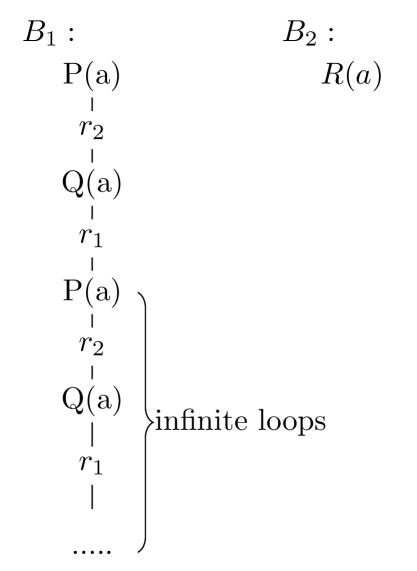
The image depicts a state transition diagram illustrating two blocks, B1 and B2, with a repeating sequence of states and transitions within B1. The diagram highlights the presence of infinite loops within the system.
### Components/Axes
The diagram consists of two labeled blocks:
* **B1:** Located on the left side of the image.
* **B2:** Located on the right side of the image.
Within B1, the following states and transitions are visible:
* **P(a)**: A state labeled "P(a)".
* **r2**: A transition labeled "r2".
* **Q(a)**: A state labeled "Q(a)".
* **r1**: A transition labeled "r1".
* The sequence P(a) -> r2 -> Q(a) -> r1 repeats infinitely.
B2 contains a single state:
* **R(a)**: A state labeled "R(a)".
A curved bracket with the text "infinite loops" points to the repeating sequence of states within B1. An ellipsis (".....") indicates the continuation of the loop.
### Detailed Analysis / Content Details
The diagram shows a clear flow within block B1:
1. The system starts in state P(a).
2. It transitions to state Q(a) via transition r2.
3. It transitions to state P(a) via transition r1.
4. This sequence repeats indefinitely, forming an infinite loop.
Block B2, containing state R(a), appears isolated and does not interact with B1. There are no transitions shown connecting B1 and B2.
### Key Observations
* The primary feature of the diagram is the infinite loop within B1.
* B2 is disconnected from the loop and appears to represent an independent state or system.
* The diagram does not provide any information about the conditions that trigger the transitions (r1 and r2) or the meaning of the functions P(a), Q(a), and R(a).
* The diagram is purely structural, showing the possible states and transitions without specifying any timing or probabilities.
### Interpretation
The diagram likely represents a system with a potential for indefinite cycling within a specific component (B1). The infinite loop suggests a lack of exit conditions or a design flaw that prevents the system from reaching a stable state. The isolated block B2 could represent a separate, unrelated part of the system or a potential destination state that is never reached due to the loop in B1.
The diagram is a simplified representation and lacks details about the underlying mechanisms. It serves as a visual warning about the possibility of infinite loops and the need for careful design to ensure system stability. The functions P(a), Q(a), and R(a) likely represent operations or processes, but their specific meanings are not revealed by the diagram. The transitions r1 and r2 could be triggered by events, conditions, or simply time. Without further information, it is difficult to determine the exact behavior of the system.