## Diagram: Logical Process Flow with Infinite Loop
### Overview
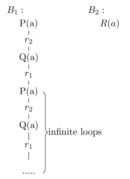
The image displays a technical diagram comparing two labeled processes or branches, designated as **B₁** and **B₂**. **B₁** depicts a vertical, repeating sequence of logical statements and rules that form an infinite loop. **B₂** shows a single, terminal logical statement. The diagram is presented on a plain, light gray background with black text and lines.
### Components/Axes
The diagram is divided into two distinct vertical sections:
* **Left Section (B₁):** A column of text elements connected by vertical lines, indicating a flow or sequence.
* **Right Section (B₂):** A single text element positioned to the right of the B₁ column.
**Labels and Text Elements:**
* **Top Labels:** `B₁ :` (top-left) and `B₂ :` (top-right).
* **B₁ Sequence (from top to bottom):**
1. `P(a)`
2. `r₂` (enclosed in a faint gray box)
3. `Q(a)`
4. `r₁` (enclosed in a faint gray box)
5. `P(a)`
6. `r₂` (enclosed in a faint gray box)
7. `Q(a)`
8. `r₁` (enclosed in a faint gray box)
9. `......` (ellipsis)
* **B₂ Element:** `R(a)`
* **Annotation:** A curly brace `}` spans the repeating section of B₁ (from the second `P(a)` to the ellipsis), with the label `infinite loops` placed to its right.
### Detailed Analysis
**B₁ Process Flow:**
1. The sequence initiates with the statement `P(a)`.
2. A vertical line connects `P(a)` to a boxed rule or transition labeled `r₂`.
3. `r₂` connects to the statement `Q(a)`.
4. `Q(a)` connects to a boxed rule or transition labeled `r₁`.
5. `r₁` connects back to the statement `P(a)`, completing one cycle.
6. This cycle (`P(a)` → `r₂` → `Q(a)` → `r₁` → `P(a)`) is shown to repeat, as indicated by the second identical cycle below the first.
7. The sequence terminates with an ellipsis (`......`), signifying continuation.
8. The curly brace explicitly labels this repeating pattern as `infinite loops`.
**B₂ Component:**
* Contains only the statement `R(a)`. There are no connecting lines or rules shown, suggesting it is either a standalone fact, a goal, or a terminal state not involved in the looping process of B₁.
**Spatial Grounding:**
* The `B₁ :` and `B₂ :` labels are positioned at the top of their respective columns.
* The `infinite loops` annotation is placed to the right of the B₁ column, vertically centered against the repeating segment it describes.
* The boxed rules (`r₁`, `r₂`) are visually distinct from the unboxed statements (`P(a)`, `Q(a)`, `R(a)`).
### Key Observations
1. **Cyclic Structure:** B₁ demonstrates a clear, two-step cyclic dependency between `P(a)` and `Q(a)`, mediated by rules `r₂` and `r₁`.
2. **Infinite Regress:** The diagram explicitly identifies this cycle as an infinite loop, meaning the process within B₁ has no terminating condition.
3. **Asymmetry:** B₂ (`R(a)`) is presented as separate and distinct from the looping mechanism of B₁. Its relationship to the B₁ process is not defined by any visible connectors.
4. **Notation:** The use of parentheses `(a)` suggests `P`, `Q`, and `R` are predicates or functions applied to a common argument or variable `a`. The subscripts on `r` denote distinct rules or relations.
### Interpretation
This diagram likely illustrates a concept from formal logic, computer science (e.g., program semantics, state machines), or automated reasoning.
* **What it demonstrates:** It contrasts a non-terminating computational or logical process (B₁) with a potentially stable or goal state (B₂). The B₁ loop represents a situation where applying rule `r₂` to `P(a)` yields `Q(a)`, and applying rule `r₁` to `Q(a)` yields `P(a)` again, creating a perpetual cycle with no progress toward a conclusion or a different state.
* **Relationship between elements:** `R(a)` in B₂ may represent a desired conclusion, an alternative fact, or a state that is unreachable from the B₁ loop. The lack of connection implies that the infinite loop in B₁ prevents the derivation or achievement of `R(a)`.
* **Underlying meaning:** The diagram serves as a visual proof or warning about a specific logical configuration that leads to non-termination. In the context of a technical document, it could be used to explain a flaw in a system's design, a paradox in a logical theory, or the behavior of a particular algorithmic pattern. The core message is the identification and isolation of a self-referential, unproductive cycle.