## Diagram: Block Process Flow with Infinite Loop
### Overview
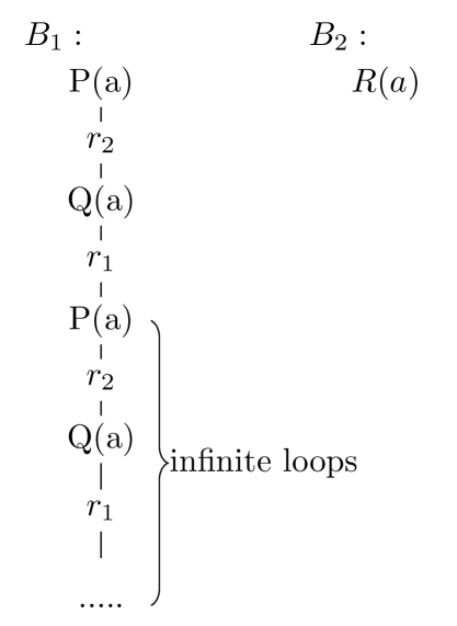
The diagram illustrates two blocks, **B₁** and **B₂**, representing sequential processes. **B₁** contains a cyclical loop with alternating components **P(a)** and **Q(a)**, while **B₂** is a linear process labeled **R(a)**. The loop in **B₁** is explicitly marked as "infinite loops" via a curly brace enclosing repeated steps.
### Components/Axes
- **Blocks**:
- **B₁**: Contains a repeating sequence of **P(a)** → **r₂** → **Q(a)** → **r₁** → **P(a)**.
- **B₂**: A single step labeled **R(a)**.
- **Labels**:
- **P(a)**, **Q(a)**, **R(a)**: Functions or processes.
- **r₁**, **r₂**: Rectangular components (likely registers or intermediate states).
- **Flow**:
- Arrows indicate directional flow between components.
- Curly brace labeled "infinite loops" groups the cyclical steps in **B₁**.
### Detailed Analysis
- **B₁ Process**:
1. **P(a)** → **r₂**: Input **P(a)** is processed and stored in **r₂**.
2. **r₂** → **Q(a)**: Output from **r₂** feeds into **Q(a)**.
3. **Q(a)** → **r₁**: Result of **Q(a)** is stored in **r₁**.
4. **r₁** → **P(a)**: Output from **r₁** loops back to **P(a)**, restarting the cycle.
- **B₂ Process**:
- Linear flow: **R(a)** is a standalone process with no feedback or repetition.
### Key Observations
- **Infinite Loop**: The cyclical nature of **B₁** suggests a perpetual process unless externally interrupted.
- **Component Roles**:
- **r₁** and **r₂** act as temporary storage or state holders between **P(a)** and **Q(a)**.
- **B₂**’s simplicity contrasts with **B₁**’s complexity, implying different functional purposes.
### Interpretation
- **System Behavior**:
- **B₁** represents a feedback-driven system where outputs of **Q(a)** influence subsequent inputs to **P(a)**. This could model iterative algorithms, state machines, or recurrent processes.
- **B₂**’s linearity suggests a one-time operation, possibly a final step or independent task.
- **Design Implications**:
- The infinite loop in **B₁** may require safeguards (e.g., termination conditions) to prevent resource exhaustion.
- **r₁** and **r₂** highlight the importance of intermediate states in maintaining process continuity.
- **Anomalies**:
- No explicit termination condition is shown for **B₁**, raising questions about system stability.
- **B₂**’s isolation from **B₁** implies modularity but lacks context for integration.
This diagram emphasizes the interplay between cyclical and linear processes, with **B₁**’s infinite loop as the central focus. The absence of numerical data or termination criteria leaves room for further investigation into system constraints and optimization opportunities.