# Unknown Title
## History of Scientists´ Elimination of Naive Beliefs about Movement - The testing of the theories of Galileo in his lifetime on board of a galley -
## ABSTRACT
Throughout the early history of Science the heliocentric world model was refused because it contradicted the thoughts of Aristotle and the medieval 'Impetus' theory of movement. Even Galileo's sky observations did not lead to any acceptance of the heliocentric model, because scientists derived from Aristotle's physics that the earth was static. It was not until 1640 when Gassendi proved the principle of inertia on a moving galley, as well as Galileo's laws of free fall with a giant wheel that 'impetus-physics' which incorporated naive beliefs about movement was abandoned. To understand the methods of calculating movement, novice students can be stitmulaed by using these initial experiments based on the dynamics of a ship movement and not rely on naïve approach. This can help novice students to attain a concept change from naïve to scientific conceptions about movement.
Modern students who study movement were found to harbour many of the same naive beliefs as our scientific forefathers. The history behind the elimination of these naive beliefs is presented here in order to help encourage elimination of these naive beliefs. Several studies found these naive beliefs to be held by novice students today. These naive beliefs held in the Science of movement have posed major problems for teaching novice students. Conflicting methods of modelling these movements have been the source of much controversy over time as concepts changed. Considering a conceptual change in history can be helpful in education.
## INTRODUCTION: Concept change
In the teaching of Science usually the naive belief of students has to be changed (Chi 1981). For example, the naive belief `there is no motion without a force` should be replaced with the expert belief `there is no acceleration without a force` (diSessa 1998). Literature holds many empirical findings about eliminating naive beliefs (Chi 1994). Concept change is triggered when two concepts are in conflict and the class has to decide which concept best resolved the problem, and sees how the replacement concept explained the demonstration or quantitative problem, for example motion of a dropped object (Kalman 2004). The idea is that the
evaluation of a theoretical framework does not occur until there is an alternative to produce the conceptual ecology. The specific failures such as being faced with an anomaly are an important part of this ecology (Posner 1982).
Here we demonstrate `teaching approaches in science education in the light of knowledge and understanding of the history of science` (Strike 1982) with a crucial experiment in history, which caused a concept change of scientists. This way recall of historic experiments helps students to eliminate naive beliefs. Context setting of the problem can have a significant influence on students´ reasoning and on concept change (Bao 2002). Concept change to explain the day/night cycle by the rotation of earth rather than a moving sun and a stationary earth is difficult because of students´ ontological and epistemological presuppositions (Vosniadou 1992). In order to achieve conceptual change, the presuppositions have to be subjected to experimentation and falsification (Vosniadou 1994). For example the concept of inertia is tested by the force concept inventory (a ball leaving a circular path), only 5% of all students answered correctly (the path tangential to the circle) independent of distracters in the multiple-choice answers (Rebello 2004, question 7). There are similar results concerning a ball falling from a moving airplane (Rebello 2004, question 14). This is explained by diSessa (1993) by phenomenological primitives used by students (p-prims, diSessa 1998). Since ´both learning and the history of science requires us to understand how conceptions change´ (Strike 1982), we investigate both the concept change from Medieval to Newtonian mechanics as well as the first statement of principle of inertia in this article.
## DATA COLLECTION. Elimination of naive beliefs about movement in history
A study is conducted here in which the history behind the elimination of common naive beliefs about movement by scientists is presented in order to help encourage it (Monk 1998). It is demonstrated finally that these naive beliefs are still found to be held by novice students today. Archimedes of Syracuse mentioned in his script 'The Calculator of Sands' that an early Greek astronomer named Aristarch explained the movements in the sky by a theory that the earth circulates around the sun like the other planets do. But no one believed that, because the earth seemed to stand still (Ley 1963). The same happened when Copernicus, who gave his name to the modern heliocentric system, claimed the same thing (Ley 1963). In the time of Galileo science still thought about the world in Aristotle's terms of dichotomy meaning that the planet earth is made up of the elements water, air, fire and earth while the sky, the other planets as
well as the stars, are made of aether. Dichotomy was seriously shaken by Galileo's observations of the sky by telescope laid down in his famous script 'Sidereus Nuncius' (News from New Stars 1610 / 1611, Galileo 1967). However, the scientific world did not accept these findings as proof of the heliocentric system, because science was used to a redesigned kind of physics of Aristotle's called the 'theory of Impetus'(Ibn Sinha 1885/86). This theory claimed the necessity of a `continuous mover` as a cause of every movement (Abu´l Barakat 1939), in modern algebraic language 'velocity is a force divided by resistance', this idea was elaborated on by many a scientist such as Avicenna (965-1039) and Albert of Saxony (1316-1390). However, scientists of antiquity as well as Arabian and Renaissance became aware of contradictions to observations as well as other antiquity theories such as the atomic theory of Epicures. Even simple observations like the trajectory of an arrow caused enormous difficulties within the theory of Impetus. Epicures (341-270 B.C.) described atoms as not infinitely small, invisibly small and continuously in movement. This theory of atoms contradicts Aristotle's physics and the impetus theory. Consequently, atomic theory was abandoned in medieval times as well as in 16 th century physics (Sambursky 1974).
In modern physics force is the cause of the change of movement (acceleration), contrarily, impetus calls for a cause for movement at any time based on Aristotle's claims for rest as the privileged and natural state on earth (Brown 2006). Based on these ideas, Aristotle's, Ptolemaist, and Thycho Brahe, amongst many, claimed that, provided the earth rotates in an easterly direction, a stone thrown up would come down in the west as long as earth moved in an easterly direction during the time of the throw, and birds and clouds would drift rapidly in an westerly direction. Since this cannot be observed, it should be reasoned that earth stays still and does not move (Sambursky 1974). Arguing that way the heliocentric ideas of Aristarch from Samos, Copernicus and Galileo have all been rejected. Even Galileo's revolutionary observations of mountains on the moon, of spots on the sun, phases of Venus and four moons encircling Jupiter made by a telescope in 1609 and in 1610 all contradicting the antiquity system of Ptolemaist did not change the situation (Galileo 1957). The seeming stillness of the earth was the major point in both the cases in the courts of inquisition against Galileo in 1516 and 1533, which led to the denouncement of the 'Dialogue concerning the chief world systems' by Galileo.
Galileo used the principle of inertia in his arguments in the 'Dialogue'. On the second day of the 'Dialogue' Salviati, who is Galileo's spokesman of the heliocentric system, claims a stone falling down the mast of a moving ship will hit the ground at the foot of the mast and will not
drift to the stern as was claimed by Aristotle. Simplicio, Aristotle's spokesman of the Ptolemaic system, does not accept this because that assertion is a claim and has never been proven (Galileo 1967). This dialogue resembles teaching physics to novice students holding naive beliefs about movement. Such an experiment with a moving ship would indeed have been too elaborate for Galileo. In this very situation this crucial experiment with the ship became reality with the help of the French priest and scientist Gassendi.
This experiment can help eliminate naive beliefs held by novice students today.
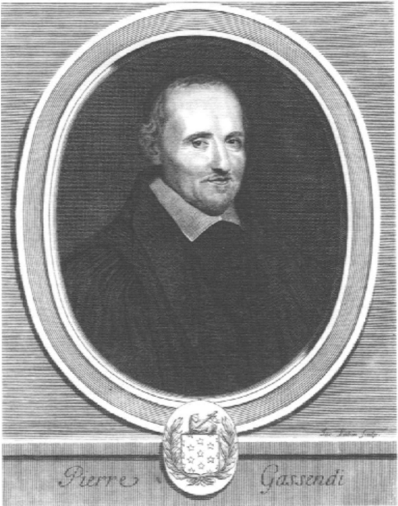
Fig. 1 Portrait of Pierre Gassendi 1592-1655, from: Egan , 1964
<details>
<summary>Image 1 Details</summary>
### Visual Description
\n
## Portrait Engraving: Pierre Gassendi
### Overview
This is a black and white historical portrait engraving, likely from the 17th or 18th century. It depicts a man, identified by the text below as Pierre Gassendi, presented within an oval frame. The style is formal and typical of scholarly or aristocratic portraits of the early modern period.
### Components/Axes
The image is composed of several distinct elements arranged vertically:
1. **Main Portrait (Center):** An oval-shaped engraving containing a bust-length portrait of a man.
2. **Frame:** A multi-layered oval frame surrounds the portrait. The outermost layer features fine, horizontal hatching lines.
3. **Coat of Arms (Bottom Center):** A small, circular emblem is positioned directly below the oval frame, overlapping its bottom edge. It contains a heraldic shield.
4. **Text Inscription (Bottom):** Below the coat of arms, a horizontal band contains text.
5. **Signature (Bottom Right):** A small, cursive signature is etched into the background hatching to the right of the oval frame.
### Detailed Analysis
**Subject Description:**
* The subject is a middle-aged man with a receding hairline, short curly hair on the sides, and a mustache.
* He is turned slightly to his right (viewer's left) but looks directly out at the viewer with a calm, serious expression.
* He wears a dark, heavy robe or gown with a simple, wide, white collar that lies flat against the shoulders. This attire suggests a scholar, cleric, or professional of the period.
**Textual Elements (Transcription & Translation):**
* **Primary Inscription (Bottom Center):**
* **Text:** `Pierre Gassendi`
* **Language:** French.
* **Translation:** Pierre Gassendi (This is a proper name).
* **Signature (Bottom Right):**
* **Text:** `Le Pautre sculp.`
* **Language:** French.
* **Translation:** "Le Pautre engraved [this]." ("Sculp." is an abbreviation for the Latin *sculpsit*, meaning "he/she engraved it"). This identifies the engraver, likely Jean Le Pautre (1618-1682), a French engraver.
**Coat of Arms:**
* The shield within the wreath is divided into four quarters.
* The first and fourth quarters (top-left, bottom-right) appear to contain three small, star-like charges (mullets or estoiles).
* The second and third quarters (top-right, bottom-left) contain a single, larger charge that is difficult to discern clearly but may be a bird or other figure.
* The shield is surrounded by a laurel wreath, a symbol of honor or achievement.
### Key Observations
1. **Formal Presentation:** The use of an oval frame, classical engraving technique, and inclusion of a coat of arms are conventions meant to confer dignity and status upon the subject.
2. **Direct Gaze:** The subject's direct eye contact creates a sense of engagement and intellectual presence, common in portraits of thinkers.
3. **Attribution:** The work is clearly attributed to both the subject (Gassendi) and the engraver (Le Pautre).
4. **Material:** The image is a reproduction of an engraving, evidenced by the use of parallel lines (hatching) to create tone and shadow, particularly visible in the background and on the subject's robe.
### Interpretation
This image is a formal, commemorative portrait of **Pierre Gassendi** (1592-1655), a prominent French philosopher, priest, scientist, and astronomer. The portrait's style and elements serve to legitimize and memorialize his status.
* **Social & Intellectual Context:** The inclusion of a coat of arms, even if not his familial one, was a common device in portraits of this era to associate the subject with nobility, virtue, or institutional authority. The simple, scholarly dress contrasts with the heraldic element, emphasizing his intellectual rather than aristocratic standing.
* **Artistic Collaboration:** The signature "Le Pautre sculp." highlights the collaborative nature of printed portraits in the period. The engraver (Le Pautre) was a skilled artisan who translated a painting or drawing into a reproducible print, which was crucial for disseminating the image and fame of a public figure like Gassendi.
* **Purpose:** Such an engraving would have been produced for inclusion in a book (perhaps one of Gassendi's own works), as a standalone print for collectors, or as frontispiece material. Its purpose was to create a definitive, authoritative visual record of the scholar for posterity and to circulate his likeness among an educated audience.
**In summary, this is not a data chart but a historical document. It provides the visual identity of Pierre Gassendi, attributes the artwork to engraver Jean Le Pautre, and uses symbolic elements (frame, coat of arms) to frame Gassendi as a figure of scholarly importance and dignity.**
</details>
Pierre Gassendi was born in 1592 in Champtercier in Provence; he studied theology in Aix-enProvence and Digne (Jones 1981) was consecrated as a priest (minister) in Digne and became a professor in Aix (Detel 1978, Egan 1964). Travelling frequently to Paris he co-operated with the scientific circle (salon) of Mersenne. Since scientific academies had not been founded, this circle of Mersenne was the most important scientific audience at that time.
The discussions there caused Gassendi to perform several experiments, such as:
- He repeated Pascal's measurement of ambient air pressure, also producing a vacuum renouncing Aristotle's theory of 'horror vacui'
- He observed Mercury's eclipse of sun by telescope in 1630
- He was the first to draw a map of the moon to scale; a crater was named 'Gassendi' in memory of this,
- He observed the growth as well as the solution of crystals through a microscope deriving existence of atoms from the persistence of angles in crystals (Detel 1978, Fisher 2005). .
- He discovered of the rings of Saturn before Huygens did so, describing Saturn's view through the telescope as elongated and wrinkled with handles.
He had exchanged letters with Galileo since 1625 (Detel 1978). After his death in Paris in 1655 his work about logic was printed in Tours in 1658 (Jones 1981), mentioning his experiments on a ship.
## DATA COLLECTION AND ANALYSIS. Reconstruction of the experiments aboard a galley 1640 which proved the principle of inertia and eliminated naive beliefs about motion
An understanding of the history of Science regarding motion can promote student understanding of important concepts through the process of conceptual change. The argument is that there are similarities between student naive beliefs and the early naive beliefs of motion held by scientists. Gassendi´s straightforward ship experiments demonstrated the effectiveness of inertial explanation of motion. The students themselves in an appropriate conceptual change teaching environment could perform similar experiments. Before recapping these historical events it should be noted that in 1610 Galileo published Sidereus Nuntius with discoveries of the moons of Jupiter, mountains on the moon and suns´ spots. In 1616 the inquisition forced him to mention the heliocentric system of Copernicus only as a hypothesis rather than a fact. Galileo's´ Dialogue Concerning the Two Chief World Systems comparing the heliocentric system of Copernicus with the Ptolemaic earth centred world system in a dramatic dialogue was published in Italian in 1632 but censored by the Roman Inquisition in 1633. The translation into Latin was published in 1636 in Strasbourg in protestant oriented central Europe, ignoring censorship. The 2 nd Latin edition was improved by Galileo in 1641; it became his last major work and was released all over Europe (Galileo 1957, 1967). Since Galileo
exchanged letters with Gassendi (Taussig 2004) it can be conjectured that Galileo knew the ship experiments when he was working on the 2 nd edition.
Several ship experiments performed by Pierre Gassendi in 1640 decided whether Galileo's theoretical experiment on the movement of bodies in a cabin of a ship was correct. This question was evidently answered by Gassendi positively. This episode documents the importance of access to proper experimental equipment in the testing of mechanical hypotheses, and of the necessity of political support in the present case, in which expensive military hardware was required.
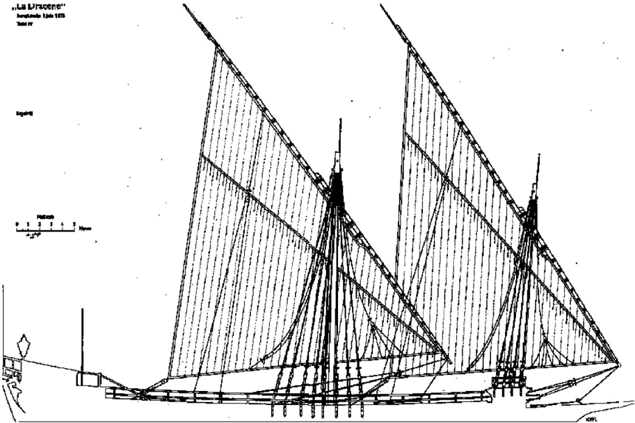
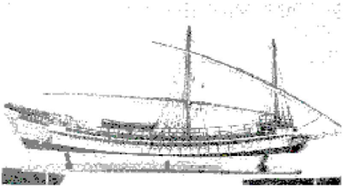
The friend and sponsor of Gassendi Louis Emanuel of House Valois became governor of Provence in 1638 and so he was in charge of the French fleet. Thus it became possible to conduct the experiment with a moving ship as proposed by Galileo. This experiment was described in his letter 'De motu impresso epistolae due', Paris, 1640 / 1642 (Gassendi 1642) in articles V and VIII superficially. Data collected from the Bavarian State Library as well as the 'Musée de la Marine' in Paris was analysed to give a report of the valid construction of Gassendi´s experiments to prove Galileo's theories. By these means the experiments can be reconstructed as follows. Ships sailing are exposed to waves and heel over and thus are not suited to perform these experiments, small rowing boats have no masts. For testing Aristotle's claims regarding motion large military galleys are required to which Galileo had no access. The experiments could be done with Louis Emanuel of House Valois and his access to the French fleet at Marseilles. The galleys of the French fleet at 1640 had a length of about 40m, the masts were about 20 m high, and attained the speed of modern sports rowing boats, about 5m/s (Mondfeld 1972). At this time Galleons of the French fleet presented two masts as shown in figures 2 and 3.
Fig. 2 French Galley in 1675, 'Musée de la Marine', Paris, from: Mondfeld 1972
<details>
<summary>Image 2 Details</summary>
### Visual Description
## Technical Diagram: Historical Sailing Vessel Plan
### Overview
The image is a black-and-white technical line drawing or plan of a two-masted sailing vessel, identified as "La Liracène." The drawing is a side elevation (profile view) showing the hull, masts, rigging, and sails. It appears to be a historical or archival document, likely from a book or technical manual, given the bibliographic notation.
### Components/Axes
**Textual Elements & Labels:**
1. **Top-Left Corner (Title Block):**
* **Line 1:** `„La Liracène"` (Primary vessel name, in French with German-style quotation marks).
* **Line 2:** `Inspirée de l'an 1825` (French: "Inspired by the year 1825").
* **Line 3:** `Tome IV` (French: "Volume IV").
2. **Left Side (Scale Bar):**
* A horizontal scale bar is present.
* **Label above bar:** `Mètres` (French: "Meters").
* **Scale markings:** The bar is divided into segments marked `0`, `1`, `2`, `3`, `4`, `5`. The unit is meters.
* **Text below bar:** `1/50` (Indicates the drawing scale is 1:50).
3. **Bottom-Left Corner:** A small, simple compass rose or directional indicator is present, showing cardinal points. The orientation of the ship is with the bow (front) to the right and the stern (back) to the left.
4. **Bottom-Right Corner:** A small, illegible mark or signature, possibly `K.W.L.` or similar.
**Diagram Components:**
* **Hull:** A single-deck hull is depicted with visible planking lines. The stern (left) features a small, raised cabin structure with a window. The bow (right) has a bowsprit extending forward.
* **Masts & Rigging:** Two masts are shown: a foremast (right) and a mainmast (left). Both are raked (angled) slightly aft. An intricate network of standing rigging (fixed ropes supporting the masts) and running rigging (ropes for controlling sails) is meticulously drawn.
* **Sails:** Each mast carries a single, large, triangular **lateen sail**. The sails are shown with vertical lines indicating their panels or reef points. The yards (the spars to which the sails are attached) are slung at an angle from the masts.
### Detailed Analysis
* **Vessel Type:** The configuration of two masts with large lateen sails is characteristic of a **xebec** or a similar Mediterranean sailing vessel, often used for trade or piracy in the 17th-19th centuries.
* **Scale & Proportion:** Using the 1:50 scale bar:
* The overall length of the hull (excluding bowsprit) appears to be approximately 15-20 meters based on visual estimation against the 5-meter scale.
* The height of the mainmast from deck to peak is roughly 2.5 to 3 times the length of the 5-meter scale bar, suggesting a height of ~12.5-15 meters.
* **Drawing Style:** The illustration is a precise, technical line drawing with no shading or color. It focuses on accurately representing the structural and rigging details for reference or construction study.
### Key Observations
1. **Historical Inspiration:** The note "Inspirée de l'an 1825" explicitly states the design is based on or inspired by vessels from that year, placing it in the late Age of Sail.
2. **Archival Context:** The "Tome IV" notation confirms this image is Plate IV from the fourth volume of a larger published work.
3. **Rigging Complexity:** The density of lines representing the rigging highlights the complexity of sailing such a vessel, requiring a skilled crew.
4. **Lateen Sail Dominance:** The entire sail plan consists of two large lateen sails, which are efficient for sailing close to the wind, a key advantage in the variable winds of coastal and Mediterranean waters.
### Interpretation
This document is a **technical reference plan** for a historical sailing ship. Its primary purpose is informational and archival, not artistic. It serves to:
* **Preserve Design:** Record the specific design characteristics of a "Liracène"-type vessel from the early 19th century.
* **Enable Study:** Allow historians, model builders, or naval architects to understand the proportions, rigging layout, and sail plan of this vessel type.
* **Provide Context:** As part of a larger volume ("Tome IV"), it contributes to a comprehensive collection of maritime designs.
The drawing emphasizes **function over form**. Every line represents a physical component—a rope, a plank, a spar. The lack of environmental context (sea, sky, crew) focuses the viewer entirely on the engineering and design of the vessel itself. The inclusion of a precise scale bar is critical, transforming the image from a mere illustration into a measurable technical document. The French text and the vessel's design strongly point to a European, likely French or Mediterranean, maritime origin.
</details>
The heights of the mast were approximately 25 m of which 20 m were accessible, thus the free fall from the mast lasted approximately 2 seconds while the ship was swiftly rowed a distance of about 10m. Thus the falling stone would be carried away 10m towards the stern. Gassendi wrote in his letter, however, that the impact of the stone was right at the foot of the mast - a very impressive contradiction to the movement theories of Aristotle as well as 'impetus' and thereby a major defeat for the entire medieval scholar system of 'Scholasticism'. Today, discussion of this experiment can be a way to help students to eliminate naive belief about movement.
Fig. 3 Galley of French fleet 1692, 'Musèe de la Marine', Paris , from: Mondfeld 1972
<details>
<summary>Image 3 Details</summary>
### Visual Description
## Technical Drawing: Historical Sailing Vessel
### Overview
The image is a black-and-white, hand-drawn technical sketch or architectural elevation of a historical sailing vessel, likely a merchant or naval ship from the Age of Sail (approx. 17th-19th century). The drawing is rendered in a sketchy, illustrative style with visible pencil or ink strokes, focusing on the ship's profile from a side (starboard) view. There is no accompanying textual data, labels, or numerical information embedded in the image.
### Components/Axes
* **Primary Subject:** A two-masted sailing ship.
* **View:** Side elevation (profile view).
* **Background:** Plain white, with no environmental context (sea, sky, land).
* **Text/Labels:** **None present.** The image contains no written words, numbers, axis titles, legends, or annotations.
* **Color:** The image is monochromatic (black lines on a white background). No color information is provided.
### Detailed Analysis
The drawing details the following structural components of the vessel:
1. **Hull:**
* A long, curved hull with a pronounced bow (front) and a raised stern (rear).
* The hull features multiple horizontal lines suggesting planking or strakes.
* A visible waterline is implied by the base of the hull.
* The stern appears to have a gallery or cabin structure with window-like markings.
2. **Masts and Rigging:**
* **Foremast:** The forward mast, positioned near the bow. It is shown with a single, large square sail furled or loosely depicted.
* **Mainmast:** The taller, central mast. It also shows a large, furled square sail.
* **Rigging:** A network of lines (shrouds, stays) is sketched, connecting the masts to the hull and to each other, providing structural support. The rigging is depicted with loose, gestural lines rather than precise detail.
3. **Deck and Superstructure:**
* A continuous deck line runs the length of the ship.
* Structures on the deck are lightly sketched, including what appears to be a raised quarterdeck at the stern and possibly a forecastle at the bow.
* Small vertical lines along the deck may represent deck fittings, cannons, or crew, but are not detailed enough for definitive identification.
4. **Additional Elements:**
* A bowsprit extends forward from the bow.
* The keel and rudder at the stern are implied by the hull's shape.
### Key Observations
* **Style:** The drawing is an artistic or preliminary sketch, not a precise engineering blueprint. Lines are loose and suggestive.
* **Completeness:** The sails are not fully drawn or billowed; they appear furled or in a state of being rigged.
* **Scale & Proportion:** The ship exhibits classic proportions of a historical sailing vessel, with the mainmast being the tallest point.
* **Absence of Data:** The image is purely illustrative. It contains **no quantitative data, labels, or textual information** to extract.
### Interpretation
This image serves as a **visual representation** rather than a source of factual or numerical data. Its purpose is likely illustrative—to convey the general form, silhouette, and key architectural features of a historical sailing ship.
* **What it Demonstrates:** The sketch effectively communicates the basic design paradigm of a two-masted, square-rigged vessel. The emphasis is on the overall shape and major components (hull, masts) rather than technical specifications.
* **Relationship of Elements:** The drawing shows the functional relationship between the hull (buoyancy and cargo), the masts (power), and the rigging (control). The raised stern suggests a command or officer's area.
* **Notable Anomalies:** There are no outliers or anomalies in a data sense, as no data is present. From an artistic standpoint, the sketch is consistent in its loose, non-technical style throughout.
* **Contextual Inference:** Based on the hull shape and two-masted configuration, this could represent a variety of vessel types, such as a brig, a schooner, or a small frigate, though a definitive classification is not possible from this sketch alone. The lack of detailed armament or cargo markings makes its specific purpose (merchant, naval, exploration) ambiguous.
**Conclusion for Technical Documentation:** This image is a **qualitative illustration**. It can be used to provide a general visual reference for the type of ship being discussed in a document but cannot be used as a source for measurements, labels, or specific technical data. Any technical details about the vessel would need to be sourced from accompanying text or separate schematics.
</details>
Gassendi performed other experiments aboard the moving ship. He let bowls down the deck once from the stern and once from the bow of the ship rolling one time in and the other time
against the movement of the vessel. They arrived at the same time. The galleys of the French fleet in 1640 had 1- to 36 - pound cannons aboard. The deck was elevated at both ends (stern 1972, Risch 2007). If you let a cannonball roll from either side, it would attained the speed of about 2.5 m/s taking into account the energy of rotation, this is less than the speed of the boat of about 5m/s. If Aristotle's theories about movement and the 'impetus' theory were right, then the cannonball released at the stern would not even move toward amidships, but move away towards the stern. This again was an impressive contradiction to the Aristotle and 'impetus' theories of movement and thereby a major defeat for all medieval physics as well as a demonstration today helping novice students to eliminate naive beliefs.
and bow) about 0.5m with respect to amidships, along a length of 17 m respectively (Mondfeld Having completed experiments aboard the moving ship, Gassendi has written the principle of inertia for the first time as it is used today in article XVI of his first 'de motu' letter: 'You will ask in passing what would happen to that stone which I claimed could be imagined in empty space if it were roused from its state of rest and impelled by some force. I answer that it is probable that it will move indefinitely in a uniform fashion, slowly or rapidly, depending on whether a small or great impetus had been imparted on it. I take my proof from the uniformity of the horizontal motion I have already explained since it would apparently not stop for any other reason than then influence of perpendicular motion... would not be accelerated or slowed down, and therefore would never stop.' (Detel 1978, Fisher 2005). The first two 'de motu' letters were addressed to Pierre Dupui in Paris in November and December 1640 and were published in 1642 (Brush 1972). Galileo's name is used today with the principle of inertia; he claimed this principle before for rotary motions alone (Galileo 1967, Brown 2006). High expenses for the ship's experiments with French state galleys and more than one hundred participants including persons of importance gave these refusals of Aristotelian physics and scholastic teachings credibility and public focus far beyond the borders of France (Taussig 2004). Due to expenses, the number of participants and high prestige of galleys, which had been involved in state races (Rambert 1931); this can be called the first 'big Science' experiment. This paved the way for wide acceptance of Galileo's findings and the heliocentric model as well as scientific revolution. These experiments can be used to eliminate naive beliefs about movement found to be held by novice students.
## METHODOLOGY. Free fall experiments to eliminate naive beliefs about movement
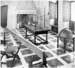
The 'de mute' letters took away the strongest objection against the heliocentric model by disproving Aristotelian physics. However, rejection of the findings of Galileo did not cease. Especially the 'Dialogue Concerning the Two Chief World Systems', and his experiments about free fall were still rejected. The naive beliefs about free fall kept at those times are found to be held by novice students today (Bar 1994). With his inclined plane (shown in figure 4), Galileo proved the law of odd numbers, claiming distances passed in consecutive times behave like odd numbers; in today's words, speed increases proportionally with time.
Fig. 4 Galileo's inclined plane, reconstruction in the Deutsche Museum, Munich, Germany.
<details>
<summary>Image 4 Details</summary>
### Visual Description
## Photograph: Historical Scientific Interior
### Overview
This is a monochromatic (black-and-white) photograph depicting the interior of a room that appears to be a historical scientific study, laboratory, or cabinet of curiosities. The scene is rich with period furniture and scientific instruments, suggesting a space dedicated to learning and experimentation from an era likely between the 17th and 19th centuries. The image quality is somewhat grainy, limiting the legibility of fine details and text.
### Components & Spatial Layout
The room is organized with distinct functional areas. The description below segments the image for clarity.
**Foreground (Bottom of Image):**
* **Left:** A wooden chair with a high, carved back and armrests is partially visible, angled towards the center.
* **Center/Right:** The floor is covered in a large, bold checkerboard pattern of alternating light and dark tiles, creating strong diagonal lines that draw the eye into the room.
**Midground (Central Area):**
* **Center:** A large, sturdy wooden table dominates the space. It has thick, turned legs and a lower shelf. On its surface rests a complex apparatus, likely a scientific instrument. It appears to consist of a vertical frame holding glass vessels, tubes, and possibly a balance mechanism, suggesting it could be for chemistry, physics, or natural philosophy experiments.
* **Right:** A terrestrial globe on a wooden stand is prominently placed. The globe shows continental outlines and is mounted on a circular horizon ring and a tripod base.
* **Left:** A smaller, simpler wooden table or stand is partially visible.
**Background (Top of Image):**
* **Left Wall:** A large fireplace with a prominent mantelpiece is built into the wall. Above the fireplace opening, there is a rectangular panel or plaque containing text.
* **Text Analysis:** The text on the panel is blurry and illegible in this image resolution. It appears to be multiple lines of script, but no specific words, letters, or language can be confidently deciphered. Its presence is noted, but its content cannot be extracted.
* **Right Wall:** A tall window with multiple panes (a mullioned window) allows light into the room. The window is flanked by wooden shutters or paneling.
* **Furniture:** Against the back wall, to the right of the fireplace, sits a dark wooden cabinet or chest of drawers.
### Detailed Analysis
* **Primary Subject:** The central table with its intricate instrument is the focal point, indicating the room's primary function as a workspace for empirical investigation.
* **Secondary Elements:** The globe signifies an interest in geography, astronomy, or navigation. The fireplace provides warmth and a traditional domestic element, contrasting with the scientific tools.
* **Architectural Features:** The room has high ceilings and substantial architectural details (deep window recess, large fireplace), suggesting it is part of a significant building, such as a university, manor house, or institutional library.
* **Lighting:** Natural light enters from the window on the right, casting soft shadows and highlighting the textures of the wood and the floor pattern.
### Key Observations
1. **Juxtaposition:** The image captures a blend of domestic comfort (fireplace, chairs) and rigorous scientific inquiry (apparatus, globe).
2. **Era Indicators:** The style of the furniture (turned legs, heavy wood), the globe design, and the type of scientific instrument are consistent with pre-industrial or early industrial European technology.
3. **Image Limitation:** The photograph's resolution and monochrome nature prevent the extraction of specific data, textual content, or fine details on the instruments. The illegible text above the fireplace is a notable missing piece of information.
4. **Spatial Composition:** The checkerboard floor creates a strong perspective grid, emphasizing the depth of the room and leading the viewer's gaze from the foreground chair to the central table and back to the fireplace.
### Interpretation
This photograph documents a **historical "philosopher's study" or early laboratory**. It visually represents the Enlightenment-era ideal of the gentleman scientist or scholar, where global knowledge (symbolized by the globe) was pursued through hands-on experimentation (the table apparatus) within a personal, curated space.
The room is not a modern, sterile lab but a lived-in environment where intellectual pursuit was integrated with daily life. The illegible text above the fireplace likely contains a motto, dedication, or identification of the room's owner or purpose, which would be crucial for precise historical context but is lost here. The image's value lies not in providing quantifiable data, but in offering a qualitative glimpse into the material culture of historical science, showing the tools, setting, and aesthetic of a pre-modern research environment. The careful arrangement suggests the space was also meant to be displayed, reflecting the owner's status and intellectual identity.
</details>
This is in contrast to medieval scholastic physics claiming speed would increase in equal steps with distance deriving this from the writings of Aristotle. This would yield to an exponential increase of distance with time. Having no modern clock, Galileo probably used his heartbeat or a water clock as a measure of time (Crawford 1996). Such poor accuracy could not clearly distinguish scholastic teaching from Galileo's law of free fall. Galileo himself describes precisely a comparison of time intervals of free fall in his 'Dialogue Concerning the Two Chief World Systems': He drops ammunition for a musket as well as a cannonball from the inclined tower of Pisa, both hit at ground the same time (Galileo 1967). It is not clear if he really performed this experiment.
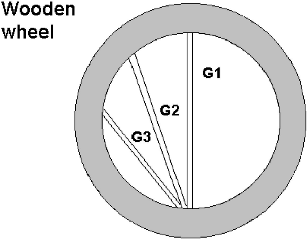
For a final proof of Galileo's law of free-fall, Gassed replaces measurement of time by time difference in his shrewd wheel of free fall (figure 5). This treadmill wheel with almost 4m diameter contained three glass tubes, which guided three bodies falling simultaneously. They arrived the same time proving Galileo's law of free fall.
Since the wheel represents Thales´ circle, force accelerating the bodies as well as distance are diminished by the same factor (cosine) resulting in the same time of fall, provided Galileo's law
holds. The time would not be the same if speed would increase proportionally with distance, as was claimed by scholastic theory.
Fig. 5, Gassendi´s wheel of free fall with three glass tubes G1 to G3
<details>
<summary>Image 5 Details</summary>
### Visual Description
## Diagram: Wooden Wheel Segmentation
### Overview
The image displays a simple, schematic diagram of a circular object labeled as a "Wooden wheel." The diagram is a top-down, two-dimensional line drawing with minimal shading. It illustrates the wheel's structure, highlighting an outer rim and an inner area divided into three distinct segments labeled G1, G2, and G3.
### Components/Axes
* **Primary Object:** A circle representing a wheel.
* **Outer Rim:** A thick, gray-shaded annular ring forming the perimeter of the wheel.
* **Inner Circle:** The white area enclosed by the rim.
* **Dividing Lines:** Three straight black lines radiating from a common point at the bottom of the inner circle to the inner edge of the rim, partitioning the inner circle into three segments.
* **Labels:**
* **Title:** "Wooden wheel" (located in the top-left corner, outside the diagram).
* **Segment Labels:** "G1", "G2", "G3" (each placed within its respective segment in the inner circle).
### Detailed Analysis
The diagram is composed of the following spatially distinct elements:
1. **Header/Title Region (Top-Left):** Contains the text "Wooden wheel" in a plain, sans-serif font. This text is not part of the wheel graphic itself but serves as its title.
2. **Main Diagram (Center):** The wheel graphic.
* **Outer Rim:** A uniform, gray-colored band. Its thickness is consistent around the entire circumference.
* **Inner Segments:** The white inner circle is divided by three lines that all originate from the same point at the very bottom (6 o'clock position) of the inner circle's boundary.
* **Segment G1:** The largest segment, occupying the right side of the inner circle. It is bounded by a vertical line going straight up from the origin point and the rim.
* **Segment G2:** A medium-sized, wedge-shaped segment located to the left of G1. It is bounded by the vertical line (shared with G1) and a second line angled to the left.
* **Segment G3:** The smallest segment, located to the left of G2. It is bounded by the line shared with G2 and a third line angled further to the left.
* **Label Placement:** The labels "G1", "G2", and "G3" are positioned roughly in the center of their respective segments. "G1" is in the large right segment, "G2" is in the middle wedge, and "G3" is in the smallest left wedge.
### Key Observations
* The three dividing lines are not spaced evenly. The angular space allocated to each segment is clearly unequal, with G1 > G2 > G3.
* All dividing lines converge at a single point on the inner circumference, suggesting a common origin or axis point for the segmentation.
* The diagram is purely schematic. It contains no numerical data, scales, axes, or indications of material properties beyond the title "Wooden."
* The use of "G" prefixes for the labels (G1, G2, G3) is a common convention for denoting groups, grades, or generations.
### Interpretation
This diagram is a conceptual model, not a technical drawing with precise measurements. Its primary purpose is to visually communicate that the "Wooden wheel" is composed of three distinct parts or categories, labeled G1, G2, and G3.
The unequal sizing of the segments is the most significant piece of information conveyed. It strongly implies a hierarchy, proportion, or distribution among the three components. This could represent:
* **Resource Allocation:** G1 might represent the largest portion of material, cost, or functional importance.
* **Process Stages:** The segments could illustrate phases in a workflow, with G1 being the primary or longest stage.
* **Categorical Division:** The wheel might be a metaphor for a whole system divided into three groups of varying significance or size.
The converging lines suggest that all three segments (G1, G2, G3) are fundamentally connected to or derived from a single source, base, or starting condition represented by the convergence point at the bottom. The diagram effectively asks the viewer to consider the relationships and relative weights of these three "G" components within the whole system of the wheel.
</details>
This experiment could be repeated everywhere improving acceptance of Galileo's laws of free fall. In our times it can still serve as an impressive demonstration for students. The simultaneous arrival of three falling bodies is more convincing to novice students than digital readouts of computers or counters as it is used in many present day classroom experiments about free fall.
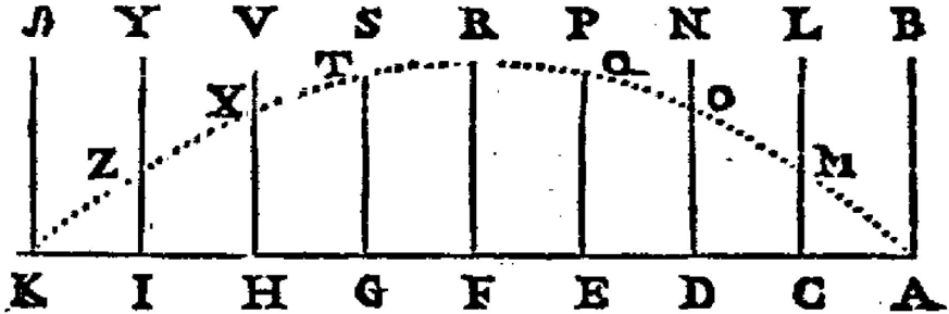
Discussing free fall in his 'de mutu' letter, Gassendi draws a parabolic curve of throw claiming that speed is diminished as a body is thrown up the same way as it increases falling down following Galileo's law of odd numbers ('reciproce', 'de motu' article VII).
Fig. 6. Parabolic path of body thrown, possibly the first drawing of physics in a modern coordinate system, from Gassendi, 1642.
<details>
<summary>Image 6 Details</summary>
### Visual Description
## Diagram: Labeled Trend Curve with Vertical Divisions
### Overview
The image is a black-and-white technical diagram, likely from a historical or scientific text. It depicts a dotted curve plotted across a series of vertical divisions. Each division is labeled with a letter at the top and a different letter at the bottom. Specific points along the curve are also labeled with letters. The diagram appears to illustrate a trend or relationship across a sequence of categories or intervals.
### Components/Axes
* **Vertical Divisions:** There are 9 vertical lines, creating 8 intervals.
* **Top Labels (Left to Right):** J, Y, V, S, R, P, N, L, B.
* **Bottom Labels (Left to Right):** K, I, H, G, F, E, D, C, A.
* **Curve:** A dotted line forming an inverted U-shape or bell curve.
* **Curve Point Labels (Left to Right along the curve):** Z, X, T, Q, O, M.
* **Spatial Layout:** The top and bottom labels are aligned vertically. The curve originates near the bottom-left corner (near point K/J), rises to a peak in the central region (between divisions S/R and R/P), and descends to the bottom-right corner (near point A/B).
### Detailed Analysis
* **Trend Verification:** The dotted line shows a clear single-peak trend. It slopes upward from the leftmost point (Z) to a maximum near the center, then slopes downward to the rightmost point (M).
* **Point Placement & Label Cross-Reference:**
* **Point Z:** Located on the curve between the first and second vertical lines (between J/K and Y/I). It is the lowest point on the left side.
* **Point X:** Located on the curve between the second and third vertical lines (between Y/I and V/H). It is higher than Z.
* **Point T:** Located on the curve between the third and fourth vertical lines (between V/H and S/G). It is near the ascending peak.
* **Peak Region:** The highest point of the curve appears to be in the interval between the fourth (S/G) and fifth (R/F) vertical lines, and possibly extending into the sixth (P/E). No single point label is at the absolute apex.
* **Point Q:** Located on the curve between the sixth and seventh vertical lines (between P/E and N/D). It is on the descending slope.
* **Point O:** Located on the curve between the seventh and eighth vertical lines (between N/D and L/C). It is lower than Q.
* **Point M:** Located on the curve between the eighth and ninth vertical lines (between L/C and B/A). It is the lowest point on the right side.
* **Data Table Reconstruction:** The diagram does not contain numerical data. It presents a qualitative relationship using labeled positions.
### Key Observations
1. **Asymmetry:** The curve is not perfectly symmetric. The ascent from Z to the peak appears slightly steeper than the descent from the peak to M.
2. **Labeling Scheme:** The top and bottom letters do not follow a simple alphabetical sequence. They may represent specific categories, states, or measurement points in a process.
3. **Peak Location:** The maximum value of the plotted trend occurs in the central third of the diagram, specifically in the region bounded by the vertical lines for S/G, R/F, and P/E.
4. **Discrete Points on a Continuous Trend:** The labeled points (Z, X, T, Q, O, M) highlight specific instances along the continuous dotted trend line.
### Interpretation
This diagram is a conceptual representation of a unimodal distribution or a process that rises to a climax and then falls. The vertical lines segment the domain into distinct phases or categories. The letters likely serve as identifiers for these phases (top row) and possibly their corresponding states or outcomes (bottom row).
The curve demonstrates that the measured attribute or phenomenon is minimal at the initial (J/K) and final (B/A) stages, reaches its maximum intensity in the middle stages (around S/G to P/E), and then diminishes. The labeled points (Z, X, T, Q, O, M) could represent critical thresholds, sample points, or named states within this process.
Without additional context, the specific meaning of the letters is unknown. However, the structure is classic for illustrating concepts like a product life cycle, a reaction progress, a population growth curve, or a signal strength profile across a sequence. The deliberate asymmetry might indicate that the process of building up to the peak is different in nature or rate from the process of decline.
</details>
This graphic representation (Figure 6) of Galileo's law of odd numbers is possibly the first visualisation of a law of physics in a modern co-ordinate system. His arguments, which reciprocate Galileo's law of diminishing odd numbers when a body is thrown up, imply invariance of physics laws with respect to time variance.
After his death the 'Institutio Logica' (Jones 1981) was published in Tours trying to simplify Aristotle's logic by a new scheme. The fourth part concerns methods of logic arguing and in its fourth canon he stresses logical implications of his experiments on a moving ship. Canon four conjectures that both reason and senses have to be taken into account arguing logically. The senses, however, have to be trusted more than reason, because 'there is the possibility that the reasoning is an inaccurate estimate or surface explanation only, the true reason for the phenomenon appearing to the senses as it does remaining hidden. For instance, although reason would at first persuade us that an arrow fired from the stern of a moving ship would fall not upon the same stern but into the sea some distance away, the ship having moved forward in the meantime, yet reason must give way to the senses, because experience shows us that it turns out differently and in actuality motion is imparted to the arrow not only by the bow but also by the ship itself (Jones 1981).' This example contradicts Aristotle. It is also a description of conceptual background naive beliefs held by many novice students today. The next example of Gassendi´s is based on Aristotle: '...People who used to believe that there were no people living in the Antipodes did so on the grounds that if there were they would fall downwards into the sky, but now that they have been discovered to indeed exist, this reasoning obviously loses its validity in the light of experience...'
## DISCUSSION. Consequences from Gassendi´s experiments to teaching physics
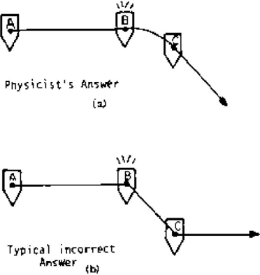
Gassendi´s experiments are important for modern psychology of perception and also for teaching. Teaching movement of earth is still a difficult task today (Parker 1998). In many investigations about perception of movement, people believed that bodies lose their speed instantaneously and stop as soon as the force driving ceases. The psychologist McCloskey found that most students believe a ball dropped while running will fall down not in a parabolic fashion but abruptly and straightaway to ground (McCloskey 1980, Caramazza 1981). This phenomenon is called 'intuitive physics' (McCloskey 1980, Krist 1993). Similarly, Clement
(1982) found that most students believe a rocket drifting in space will retain its speed before ignition (figure 7) when engines stop.
Fig. 7 Rocket path question to investigate intuitive physics.
<details>
<summary>Image 7 Details</summary>
### Visual Description
## Diagram: Physics Problem Illustration - Projectile Motion Trajectories
### Overview
The image contains two black-and-white schematic diagrams, labeled (a) and (b), stacked vertically. They illustrate two different conceptual answers to a physics problem involving the motion of an object from point A to point C, passing through point B. The diagrams contrast a correct ("Physicist's") solution with a common incorrect one.
### Components/Axes
* **Diagram (a) - Top:**
* **Label:** "Physicist's Answer" centered below the diagram, with "(a)" beneath it.
* **Components:** Three points labeled **A**, **B**, and **C**, each marked with a downward-pointing triangle.
* **Path:** A straight horizontal line connects **A** to **B**. From **B**, a smooth, downward-curving line (parabolic arc) connects to **C**. An arrowhead at the end of the curve points downward and to the right.
* **Symbol:** A starburst or explosion symbol is drawn above point **B**.
* **Diagram (b) - Bottom:**
* **Label:** "Typical incorrect Answer" centered below the diagram, with "(b)" beneath it.
* **Components:** Identical setup to (a) with points **A**, **B**, and **C** marked by triangles.
* **Path:** A straight horizontal line connects **A** to **B**. From **B**, a straight diagonal line connects to **C**. An arrowhead at the end of this line points horizontally to the right.
* **Symbol:** An identical starburst symbol is drawn above point **B**.
### Detailed Analysis
The diagrams present a visual comparison of two conceptual models for the same physical scenario.
* **Common Elements (Both Diagrams):**
* **Initial Motion:** The object travels in a straight, horizontal line from point **A** to point **B**.
* **Event at B:** The starburst symbol at **B** suggests a critical event occurs there, such as an explosion, a release, or a change in the forces acting on the object.
* **Final Destination:** The object's path ends at point **C**.
* **Critical Difference (Path from B to C):**
* **In Diagram (a) - "Physicist's Answer":** The path from **B** to **C** is a **downward-curving parabola**. This trajectory is characteristic of **projectile motion** under the influence of gravity, where the object has an initial horizontal velocity component from its motion from A to B, but is also subject to constant downward acceleration.
* **In Diagram (b) - "Typical incorrect Answer":** The path from **B** to **C** is a **straight diagonal line**. This represents a common intuitive but incorrect model where the object is assumed to travel in a straight line from its new starting point **B** to its destination **C**, ignoring the continuous effect of gravity which would curve its path.
### Key Observations
1. **Spatial Layout:** The two diagrams are presented for direct vertical comparison, emphasizing the contrast in the **B-to-C** path.
2. **Symbolic Consistency:** The identical starburst at **B** in both diagrams confirms the event at that point is the same; only the subsequent motion model differs.
3. **Directional Arrows:** The arrowhead in (a) points along the tangent of the curve (downward-right), consistent with velocity in projectile motion. The arrowhead in (b) points purely horizontally, which is inconsistent with the diagonal straight-line path shown, suggesting a possible additional error in the diagram's own logic.
4. **Labeling:** The labels explicitly frame the comparison as between a correct scientific understanding and a widespread misconception.
### Interpretation
This image is a pedagogical illustration designed to highlight a specific conceptual error in physics reasoning.
* **What it Demonstrates:** It contrasts the correct application of kinematic principles (accounting for gravity's continuous acceleration) with an intuitive but flawed "straight-line" or "impulse" model of motion. The "Physicist's Answer" correctly shows that an object with horizontal velocity, once free of its initial constraint (at point B), will follow a parabolic path due to gravity. The "Typical incorrect Answer" shows the common mistake of assuming the object instantly changes to a new straight-line trajectory toward the target.
* **Relationship Between Elements:** The horizontal line **A-B** sets up an initial condition of horizontal motion. The event at **B** (explosion/release) changes the forces, and the subsequent path **B-C** reveals the underlying physical model being used. The diagrams are a visual "spot the difference" exercise for students.
* **Notable Anomaly:** The arrowhead in diagram (b) is horizontally oriented, while the line it terminates is diagonal. This internal inconsistency might be an intentional part of the illustration to further emphasize the incorrectness of the model, or a drafting error.
* **Underlying Message:** The image teaches that correct physical prediction requires applying fundamental laws (like F=ma and the independence of motion components) continuously, not just at discrete points. It warns against relying on geometric intuition for dynamic problems.
</details>
College students were asked about an object dropped from a mast of a moving ship, most students answered the object will fall and strike the deck behind the foot of the mast rather than at the foot of the mast (Whitaker 1983). Though 'intuitive physics' ignores the principle of inertia and follows Aristotelian physics and the false idea of impetus, it has been found in many investigations about students (Reif 1987, Clement 1989, Adey 1992, DiStefano 1996a, 1996b, Gautreau 1997). It is a serious pitfall when teaching beginner's classes in physics, therefore testing scores of students in physics remain low (Driver 1989, Licht 1990).
## CONCLUSION. Possible ways to improve concept change in teaching and learning.
Beginner's difficulties in physics can be eased by the discussion of Gassendis´ experiments and repetition of these by students' observing for example falling bodies in a moving vehicle such as a car, a bus, a lorry or a boat as an out- of- school experience (Mahoy 1997). This kind of experience has been shown to improve learning (Donnelly 1998).
To ease elimination of naive beliefs about movement, each individual can recall the long way mankind took to overcome these naive beliefs.
Even a single experiment can induce a concept change in students; most efficient are hands-on experiments (Abbott 2000). Individual naive belief in physics is sometimes a recapitulation of a historic naive belief (Chi 1994). Approach to concept change is easier `in the light and understanding of the history of science` (Strike 1982). For example, computer simulation of Galileo's historic experiments with the inclined plane and water clock helped understanding of physics concepts (Borghi 1992). Suspense stories like ' Galileo and the inquisition ' raise emotions improving memory and attendance thus easing concept change, according to results of psychological research (Cahill 1994, Erk 2003).
## REFERENCES
- Abbott, D. E., Saul, J. M., Parker, G. W., Bleichner, R. J., 2000. Can one lab make the difference? Physics Education Research. American Journal of Physics Suppl., 68 (7), 560561.
- Abu`l Barakat, 1939. Hibatallah ibn ´Ali al-Baghdadi, al-Kitab al Mu´tabar . Vol. 2, Hyderabad, p.101, translation from Arabian by W. W. Mueller
- Adey, P., 1992. The CASE results: implications for science teaching. International Journal of Sci. Education, 14, (2), 137-146.
- Bao, L., Hogg, K., & Zollman, D., 2002. Model Analysis of fine structures of student models: An example with Newton´s third law. American Journal of Physics, 70, 766-778.
- Bar, V., Zinn, B., Goldmuntz, R., & Sneider, C., 1994. Children's concepts about weight and free fall. Science Education, 78 (2), 149-169.
- Borghi, L., 1992. Computer simulation of historic experiments and understanding of physics concepts, 207-215 in: Tiberghien, Andrée Intelligent learning environments and knowledge acquisition in physics [proceedings of the NATO Advanced Research Workshop on Knowledge Acquisition in the Domain of Physics and Intelligent Learning Environments] ed. by A. Tiberghien. Berlin: Springer.
- Brown, H. I., 2006. Do physicists need myths? Am. Jour. Phys., 74, 382-385.
- Brush, Craig, 1972. Gassendi, Selected works , translation. New York: Johnson Reprints.
- Cahill, L., Prins, B., Weber, M., & McGaugh, J. L., 1994. Beta-adrenergic activation and memory for emotional events . Nature, 371, 702-704.
- Caramazza, A., McCloskey, M., & Green, B., 1981. Naive beliefs in sophisticated subjects: misconceptions about trajectories of objects. Cognition , 9, 117-123.
- Chi, M. T. H., Feltovich, P. J., & Glaser, R., 1981. Categorisation and representation of physics problems by experts and novices. Cognitive Science 5, 121-152.
- Chi, M. T. H., Slotta, J. D., & DeLeeuw, N., 1994. From Things to Process: A Theory of Conceptual Change for Learning Science Concepts. Learn. Instruc., 4 (1), 27-43.
- Clement, J., 1982. Students´ preconceptions in introductory mechanics. Am. Journal Phys. , 50 (1), 66-71.
- Clement, J. , Brown, D.E., & Zietsman, A., 1989. Not all preconceptions: finding anchoring conceptions for grounding instruction on students´ intuition. International Journal of Sci. Education, 11, 554-565.
- Crawford , F. S., 1996. Rolling and slipping down Galileo´s inclined plane: Rhythms to the spheres. Am. Journal of Physics, 64, 541-546.
- Detel, W., 1978. Scientia Rerum Natura Occultarum, Methodologische Studien zum Physik Pierre Gassendis . Berlin: De Gruyter, 123-195.
- DiSessa, A. .A., 1993. Towards an epistemology of physics. Cognition and Instruction, 10 (23), 105-225.
- DiSessa, A. A. & Sherin , B. L., 1998 . What changes in conceptual change? International Journal of Science Education ; 20 (10), 1155-1191.
- DiStefano, R., 1996 (a). The IUPP evaluation: what we are trying to learn and how we were trying to learn it. Am. Journal Phys. , 64 (1), 49-57.
- DiStefano, R., 1996 (b) . Preliminary IUPP results: Student reactions to in-class demonstrations and to the presentation of coherent themes. Am. Journal Phys., 64 (1), 5868.
- Donnelly, J. F., 1998. The place of the laboratory in secondary science teaching. International Journal of Science Education, 20 (5), 585-596.
- Driver, R., 1989. Students conceptions and the learning of science. International Journal of Science Education, 11, 481-490.
- Egan, H. T., 1964. Gassendis view of knowledge , New York: Lanha.
- Erk, S., Kiefer, M., Grothe, J., Wunderlich, A. P., Spitzer, M., & Walter, H., 2003. Emotional context modulates subsequent memory effect. Neuro Image ,18, 439-447.
- Fisher, Saul, 2005. Pierre Gassendi´s Philosophy and Science - Atomism for Empiricists , Leiden& Boston: Brill, 225-276 .
- Galileo Galilei, 1957. Discoveries and Opinions of Galilei, translation St. Drake, NY: Anchor Books.
- Galilei, Galileo, 1967. Sidereus Nuncius - (news of new stars) Dialogue Concerning the Two Chief World Systems , 1638, translator St. Drake, Berkeley, CA: Univ. of Cal. Press.
- Gassendi, Pierre, 1642. de Motu Impresso a Motore translato…, Paris, 1640 / 1642, letter, Bibliotheka Windhaginna, copy of the Bavarian State Library, Munich
- Gautreau, R , & Novemsky, L., 1997. Concepts first- a small group approach to physics learning. Am. Journal Phys., 65 (5), 418-428.
- Ibn Sina, 1885 / 86. Kitab aš-Sifa, Teheran, p. 154-156, translation from Arabian by W. W. Mueller
- Jones, H., 1981. Pierre Gassendi 'Institutio Logica ' 1658, critical edition and transl., Assen, The Netherlands: Van Gorcum , 160-161.
- Kalman, C. S., Shelley, Rohar, Wells, D., 2004. Enhancing conceptual change using argumentative essays. American Journal of Physics , 72 (5), 715-717.
- Krist, H., Fieberg, E. L., & Wilkening, F., 1993. Intuitive Physics in action and judgement: Development of knowledge about projectile motion. Journal of experimental psychology, Learning, Memory and Cognition, 19 , 952-969.
- Ley, Willy, 1963. Watchers of the Sky, Viking Press, New York, N. Y.,
- Licht, P. & Thijs, G. D., 1990. Method to trace coherence and persistence of preconceptions. International Journal of Science Education , 12, (4), 403-416.
- Mahoy, K. A. & Knutton, S., 1997. Using out-of-school experience in science lessons: reality or rhetoric? International Journal of Sci. Education, 19 (7), 849-867.
- McCloskey, M., Caramazza, A., & Green, B., 1980 . Curvilinear motion in absence of external forces: naive beliefs about the motion of objects. Science, 210 , 1139-1141.
- Mondfeld, W., 1972. Die Galeere vom Mittelalter bis zur Neuzeit . Bielefeld : Delius & Klasing
- Monk; M. & Osbone , J., 1997. Placing the history and philosophy of science on the curriculum: A model for the development of pedagogy. Science Education, 81 (4) , 405242.
- Parker, J., Heywood , D., 1998. The earth and beyond: developing prim. teachers´ understanding of basic astronomical events. International Journal of Sci. Education 20, 1998 (5), 503-520.
- Posner, G. J., Strike, K.A.., & Hewson, P.W., et al.., 1982. Accommodation of a scientific conception: Toward a theory of conceptual change, Science Education, 66 (2), 211-227.
- Rambert, G., 1931. Nicolas Arnould, Intendant des Galeres à Marseille 1665-1674, Dissertation. Aix-en Provence & Marseille: Provincia ed.
- Rebello, N. S., & Zollman, D. A., 2004. The effect of distracters on student performance on the force concept inventory, American Journal of Physics, 72 (1), 116-125.
- Reif, Frederick, 1987. Interpretation of scientific or mathematical concepts: Cognitive issues and instructional implications. Cognitive Science, 11, 395-416.
- Risch, Matthias, 2007. Das erste Großexperiment der Physik auf einer Galeere: Pierre Gassendi und die kopernikanische Zeitenwende, Physik in unserer Zeit 38, (5) 249-253
- Sambursky, Shmuel, 1974. Physical Thought from the Presocratics to the Quantum Physicists. An anthology , London : Hutchinson & Co.
- Strike, K. A., & Posner, G. J., 1982. Conceptual change and science teaching, International Journal of Science Education (= European journal of Science Education) , 4 (3), 231- 240.
- Taussig, Sylvie, 2004. Gassendi, Lettres latines , 1211/ XVI; 231 (1); 172-173 (2), Aix en Provence & Paris: Tounhout editions.
- Vosniadou, S., 1992. Modelling the learner: lessons from a study of knowledge reorganisation
in astronomy, 101-111 in: Intelligent learning environments and knowledge acquisition in physics [proceedings of the NATO Advanced Research Workshop on Knowledge Acquisition in the Domain of Physics and Intelligent Learning Environments] ed. by A. Tiberghien , Springer, Berlin
Vosniadou, S., 1994. Capturing and modelling the process of conceptual change, Learning Instruction, 4, 45-69.
Whitaker, R. J., 1983. Aristotle is not dead: Student understanding of trajectory motion . Am. Journal Phys. , 51, 352-357.
## FIGURE CAPTIONS
Fig. 1 Portrait of Pierre Gassendi1592-1655
Fig. 2 French Galley in 1675, 'Musèe de la Marine', Paris, (Mondfeld 1972)
Fig. 3 Galley of French fleet 1692, 'Musèe de la Marine', Paris (Mondfeld 1972)
Fig. 4 Galileo's inclined plane, reconstruction in the Deutsche Museum, Munich, Germany.
Fig. 5, Gassendi´s wheel of free fall with three glass tubes G1 to G3
Fig. 6. Parabolic path of body thrown, possibly the first drawing of physics in a modern coordinate system
Fig. 7 Rocket path question to investigate intuitive physics.
## KEY WORDS
Galileo Gassendi Free fall Galley Principle of inertia
STICHWORTE Galilei Gassendi Freier Fall Galeere
Trägheitsprinzip