# Towards Maximizing a Perceptual Sweet Spot
**Authors**: Pedro Izquierdo Lehmann, Rodrigo F. Cadiz, Carlos A. Sing Long
## TOWARDS MAXIMIZING A PERCEPTUAL SWEET SPOT
PREPRINT
## Pedro Izquierdo Lehmann
Rodrigo F. Cádiz
Institute for Mathematical and Computational Engineering Pontificia Universidad Católica de Chile pizquierdo2@uc.cl
Department of Electrical Engineering and Music Institute Pontificia Universidad Católica de Chile rcadiz@uc.cl
## Carlos A. Sing Long ∗
Institute for Mathematical and Computational Engineering and Institute for Biological and Medical Enginering Pontificia Universidad Católica de Chile casinglo@uc.cl
May 5, 2022
## ABSTRACT
The sweet spot can be interpreted as the region where acoustic sources create a spatial auditory illusion. We study the problem of maximizing this sweet spot when reproducing a desired sound wave using an array of loudspeakers. To achieve this, we introduce a theoretical framework for spatial sound perception that can be used to define a sweet spot, and we develop a method that aims to generate a sound wave that directly maximizes the sweet spot defined by a model within this framework. Our method aims to incorporate perceptual principles from the onset and is flexible: while it imposes little to no constraints on the regions of interest, the arrangement of loudspeakers or their radiation pattern, it allows for audio perception models that include state-of-the-art monaural perceptual models. Proof-of-concept experiments show that our method outperforms state-of-the-art methods when comparing them in terms of their localization and coloration properties.
Keywords Spatial sound · sound field reconstruction · psychoacoustics · sweet spot · applied functional analysis · non-convex optimization · DC optimization
## 1 Introduction
The field of spatial sound addresses the question: how do we create a desired spatial auditory illusion over a spatial region of interest with a set of acoustic sources? [1, Chapter 2.3]. The spatial auditory illusion (SAI) occurs when acoustic sources create a sound scene that produces a desired auditory scene over a region. It is related to sound quality as described by Wierstof et al [2, Chapter 2]: 'The quality of a system as perceived by a listener is considered to be the result of assessing perceived features with regard to the desired features (of the auditory scene). ' Following Blauert, the sound scene represents the objective nature of a sound wave propagating in the physical world, whereas the auditory scene represents the imprint of the sound scene in our subjectivity, that is, the result of the auditory system perceiving and organizing sound into meaning [3]. Over the last century, several methods have been proposed to answer this. Their performance can be compared in terms of the size of the region where the SAI is achieved. In this work, we call this region the sweet spot .
∗ C. A. Sing Long is also with ANID - Millennium Science Initiative Program - Millennium Nucleus Center for the Discovery of Structures in Complex Data, and with ANID - Millennium Science Initiative Program - Millennium Nucleus Center for Cardiovascular Magnetic Resonance.
The term sweet spot is already used in panning and surround systems to describe an ideal listening position that is equally distant to all loudspeakers [4] and around which there is a limited area where a desired wavefront is correctly recreated [1, Chapter 3.1], [5]. It is also used to mean the 'area in which the spatial perception of the auditory scene works without considerable impairments' [6, Chapter 1.2]. Furthermore, in [7] the sweet area is defined as the 'area within which the reproduced sound scene is perceived as plausible, ' where plausible means the preservation of front localization and envelopment of reverberation. Our use of the term is in the spirit of the second and third ideas.
One of the earlier and most widespread spatial sound approaches is stereophony and its generalizations, sourround systems [8] and Vector Base Amplitude Panning (VBAP) [9]. These methods, also called panning techniques , adjust the level and time-delay of the audio signals for each speaker utilizing a panning law to simulate steering the perceived direction of the sound source. The possibility of this steering has been explained by the perceptual idea of summing localization and by the association model [1, Chapter 6.1]. Moreover, due to some psycho-acoustic features of the auditory system, such as the binaural decoloration mechanism, they work sufficiently well in some applications, even with few speakers [4]; they do not suffer from coloration [10]. However, they can only simulate sound sources that lay on the segments that join the speakers. Furthermore, its quality degrades rapidly as the listener moves away from the center of the target region [4].
A popular strategy to recreate an auditory scene is to directly approximate the sound wave that created it. In the literature, this strategy is called sound field synthesis , sound field reproduction or sound field reconstruction . Following Huygens' principle [11], any sound scene can be approximated accurately with a sufficiently dense arrangement of loudspeakers. However, in practice there is only a limited number of them. Three classes of commonly used methods for sound field reconstruction are mode matching methods , pressure matching methods and wave field synthesis .
Mode Matching Methods (MMM) match the coefficients in the expansion of the target and generated sound waves in spatial spherical harmonics [12]. Some well-known MMMs are Ambisonics [13], Higher-Order Ambisonics (HOA), and Near-Field Compensated Ambisonics (NFC-HOA) [14]. All of them minimize the 2 -norm of the difference between the leading coefficients. Ambisonics assumes the loudspeakers emit plane waves and uses only the leading coefficient, whereas HOA uses a larger but fixed number of coefficients. In contrast, NFC-HOA assumes the loudspeakers are monopoles. Ambisonics, HOA and NFC-HOA are designed for circular or spherical regions of interest. When approximating a plane wave, they create a central spherical region with a radius that is inversely proportional to the frequency of the source over which the sound scene is reconstructed almost identically [15]. Some variations of these methods consider a weighted mode matching problem to prioritize certain spatial regions [16], a mixed pressure-velocity mode matching problem [17], and an intensity mode matching problem [18].
Instead of using expansions in spatial spherical harmonics, Pressure Matching Methods (PMM) minimize the spatiotemporal L 2 -error between the the target and generated sound waves [19]. The magnitude of the audio signals are often penalized by their L p -norm to mitigate the effects of ill-conditioning [20, 21, 22, 23] and to enforce sparse representations [24, 25]. Typically the loudspeakers are modeled as monopoles. In most cases, the solution can only be found numerically, and the discretization of the region of interest plays an important role [26, 27]. Variations considering a mixed pressure-velocity pressure matching problem have been considered [28, 29, 30].
Finally, Wave Field Synthesis (WFS) leverages the single-layer boundary integral representation of a sound wave over a region of interest [4]. Traditional WFS [31] uses a Rayleigh integral representation to derive a solution when the speakers are modeled as dipoles lying on a line. This was later extended to monopoles [32] for 2.5D reproduction. Its reformulation, Revisited WFS [33], uses a Kirchhoff-Helmholtz integral representation along with a Neumann boundary condition to obtain a solution for an arbitrary distribution of monopoles. It has been shown that the localization properties of the auditory scene are correctly simulated by WFS and do not depend on the position of the listener over the region of interest [34]. However, this technique suffers from coloration effects due to spatial aliasing artifacts [35].
There is extensive literature analyzing these methods and comparing their performance [14, 36, 37, 38, 39], they become equivalent in the limit of a continuum of loudspeakers, differing only when using a finite number [40] of them. Although they are amenable to mathematical analysis and have computationally efficient implementations, their construction has no natural perceptual justification to produce a large sweet spot. As a consequence, the artifacts introduced by these methods, due to approximation errors, may produce noticeable, and possibly avoidable, perceptual artifacts.
An alternative to better reproduce the auditory scene is to explicitly account for psycho-acoustic and perceptual principles in the reconstruction methods [6]. The first steps in this direction were taken in [41] by proposing a simple model that aims to preserve the spatial properties of the desired auditory scene. A method to reproduce an active intensity field that is largely uniform in space was then proposed in [42]. It is based on an optimization problem yielding audio signals where at most two loudspeakers are active simultaneously. However, it makes the restrictive assumption that the target sound wave is a plane wave, and that the loudspeakers emit plane waves. In [43] the radiation method and the precedence fade are proposed. The former is equivalent to applying a PMM over a selection of frequencies that
are most relevant psycho-acoustically, whereas the latter is a method to overcome the localization problems associated to the precedence effect [44]. Finally, in [45] a PMM is extended to account for psycho-acoustic effects by considering the L 2 -norm of the differences in pressure convolved in time by a suitable filter.
We believe that there is a gap between methods that aim to directly approximate a sound wave to reproduce a desired auditory scene, and methods that leverage perceptual models to reproduce the same auditory scene. Defining the sweet spot requires a model, either theoretical or empirical, of audio perception. In this work, we introduce theoretical framework for for spatial audio perception, and we develop a method to maximize the sweet spot defined by a model within this framework. Our method is amenable to mathematical analysis, it has an efficient computational implementation, and is guided by perceptual principles. Our numerical results show that our method outperforms some state-of-the-art methods for sound field reconstruction.
The paper is organized as follows. In Section 2 we introduce the physical assumptions we make, and a theoretical framework for spatial audio perception, deferring to Appendix A the technical details. Then, in Section 3 we introduce an intuitive and readily implementable instance of our method to maximize the sweet spot defined by a model within this framework. In Section 4 we discuss the psycho-acoustic concepts that, to our knowledge, can be incorporated in the theoretical framework. In Section 5 we present an implementation of our method. In Section 6 we perform proof-of-concept numerical experiments analyzing the performance of our method, comparing its results with WFS, NFC-HOA and PMM. Finally, in Section 7 we discuss our results, the limitations of our method, and some future lines of research.
## 2 Spatial Sound Mathematical Framework
## 2.1 Acoustic framework
Consider n s loudspeakers located at positions x 1 , . . . , x n s ∈ R 3 . When the medium is homogeneous and isotropic, and each loudspeaker behaves as an isotropic point source, the physical sound wave u they generate is represented in frequency as [46, Section 2.5.2]
<!-- formula-not-decoded -->
where c s is the speed of sound, c 1 , . . . , c n s are the audio signals driving each loudspeaker, and ̂ c k is the Fourier transform of c k in time
<!-- formula-not-decoded -->
To model the spatial radiation pattern of each loudspeaker, along with time-invariant effects such as reverb [20, 47], we may use
<!-- formula-not-decoded -->
where G k is the Green function of the k -th loudspeaker. In addition to the array, we consider a region of interest Ω ⊂ R 3 such that x k / ∈ Ω ; thus, it contains no singularity in (1). On this region, we may approximate a sound wave u 0 with the array of loudspeakers as best as possible . If we had a continuum of isotropic point sources on ∂ Ω then, under suitable conditions, the simple source formulation [48, Section 8.7] shows we can reproduce u 0 exactly . However, when only a finite number of physical loudspeakers are available, we must find ̂ c 1 , . . . , ̂ c n s such that
<!-- formula-not-decoded -->
in an suitable sense for x ∈ Ω . When each G k is real-analytic on its second argument the approximation cannot be exact on any open set unless u 0 was actually generated by the speaker array [49, Corollary 1.2.5]. This suggests that perfect sound field reconstruction is impossible, and that the difference can be small only on average. In spite of this, in some subset of Ω the approximation can be perceptually accurate.
## 2.2 Perceptual framework
The comparison in (3) is between two physical quantities. To incorporate perceptual effects, we formally introduce a theoretical framework and defer the mathematical details to Appendix A.1.
The perception of an individual located at x ∈ Ω and looking in the direction represented by a unit vector θ in R 3 (or an angle in R 2 ) depends on the relation between the sound wave at the left and right ears. Hence, we consider pairs of signals u , u r so that u s = u s ( t, x, θ ) represents the wave that reaches the ear s of a listener located at x and looking in the direction θ at time t . We let u s ( x,θ ) represent the signal at ear s . From now on, let ¯ u be this vector signal, and let W be the space of all such signals. Instead of (2) we consider
<!-- formula-not-decoded -->
where H s k is the head-related transfer function [3] associating to a wave emitted by the k -th loudspeaker the sound wave reaching the ear s ; this comprises the behavior of the loudspeakers. From now on, we let W S be the set of all pairs of signals generated by model (4).
Therefore, the problem is to approximate the fixed target signal ¯ u 0 associated to the sound wave u 0 by a signal ¯ u represented as (4) that is perceptually close to ¯ u 0 . To model the perceptual dissimilarity we introduce a map D that associates to a pair ¯ u, ¯ u 0 the function D (¯ u, ¯ u 0 ) = D (¯ u, ¯ u 0 ) ( x, θ ) that quantifies the dissimilarity between the signals ¯ u and ¯ u 0 perceived by a listener located at x and looking in the direction θ . We do not make strong assumptions on D except that it is convex : for ¯ u 1 , ¯ u 2 we have
<!-- formula-not-decoded -->
for any λ ∈ [0 , 1] . We assume the dissimilarity is negligible if D (¯ u, ¯ u 0 ) ( x, θ ) ≤ 0 . Depending on the application, this may be interpreted as authenticity , i.e., ¯ u is indiscernible from ¯ u 0 , or as plausibility , i.e., some perceived features of ¯ u and ¯ u 0 show a context-reasonable correspondence [2, Chapter 2]. In Section 4 we discuss some functional forms for D .
Suppose the listeners can look only along some directions of interest Θ . We define the auditory illusion threshold as
<!-- formula-not-decoded -->
A listener located at x will perceive no noticeable differences between ¯ u and ¯ u 0 regardless of the direction she is looking if T ¯ u ( x ) ≤ 0 . Hence, the sweet spot
<!-- formula-not-decoded -->
is the region within Ω where a listener does not perceive significant differences between ¯ u and ¯ u 0 . We define a loudness discomfort threshold similarly: we assume there is a function L that associates to ¯ u the function L ¯ u = L ¯ u ( x, θ ) quantifying the loudness discomfort experienced by a listener at a location x looking in a direction θ . We also assume L satisfies (5) and we define the the loudness discomfort threshold
T
L
¯
u
(
x
) := sup
θ
∈
Θ
We assume that T L ¯ u ( x ) ≤ 0 when no discomfort is experienced. Hence, to avoid choosing a signal ¯ u that causes discomfort, we restrict our choices to
<!-- formula-not-decoded -->
Consequenty, our goal is to find a signal ¯ u ∈ W S that maximize the weighted area of the sweet spot µ ( S (¯ u )) while causing no discomfort by solving
<!-- formula-not-decoded -->
L
¯
u
(
x, θ
)
.
## 3 The SWEET-ReLU method
We introduce a particular instance of our method to approximately solve ( P 0 ) that is applicable in practice and has an intuitive interpretation. We defer the analysis of our general method to Appendix A. Let h : R → R be the Heaviside function, i.e., h ( t ) = 0 if t < 0 and h ( t ) = 1 if t ≥ 0 . Observe that
<!-- formula-not-decoded -->
Maximizing µ ( S (¯ u )) implies minimizing the second term. This is challenging due to h being piecewise constant. For ε > 0 we can approximate it by a piecewise linear function ˜ h : R → R such that ˜ h ( t ) = 0 for t < 0 , ˜ h ( t ) = t for
## Algorithm 1: SWEET-ReLU
```
```
t ∈ [0 , 1] and ˜ h ( t ) = 1 for t > 1 . For ε > 0 let ˜ h ε ( t ) = ˜ h ( t/ε ) and let ¯ u 1 ∈ W S be arbitrary. We can minimize the approximation
<!-- formula-not-decoded -->
where ( u ) + = max { 0 , u } . We interpret the first integral as the contribution from the region where we may change ¯ u 1 to decrease the auditory illusion threshold, whereas we interpret the second as the contribution of the region over which it is already too large. Thus, we proceed in a greedy manner: we let Ω 1 = Ω , and then, at the k -th iteration, we define
<!-- formula-not-decoded -->
<!-- formula-not-decoded -->
and solve to obtain ¯ u k +1 . The above problem is convex, whence ¯ u k +1 can be found using efficient algorithms. The sequence { ¯ u k } k ∈ N has at least one accumulation point, which approximates the solution to ( P 0 ) . Once the sequence has converged, we can repeat the procedure for a smaller value of ε . As the intuition behind our method suggests choosing a ¯ u 1 for which T D ¯ u 1 ≡ 0 , e.g. ¯ u 1 = ¯ u 0 , we simply choose Ω 1 = Ω in practice. By running the algorithm for increasingly smaller values of ε we obtain an increasingly accurate approximation to a solution to ( P 0 ) . We call this instance of our method SWEET-ReLU (Algorithm 1). We defer a justification of these facts to Appendix A and the deduction of this instance to Appendix A.5.
## 4 Perceptual and psycho-acoustic theory
The theoretical framework introduced aims to be flexible enough to account for a variety of perceptual and psychoacoustic models. We now present some of the perceptual and psycho-acoustic considerations that lead to models within this framework.
The spatial auditory illusion (SAI) is achieved when the imprint of the reproduced sound scene on a listener resembles a desired auditory scene. The formation of the auditory scene depends not only on the signals reaching the listener's ears but both on the listener itself [50]. Also, it may even be influenced by external visual, tactile, and proprioreceptive stimuli [51]. Formulating a model accounting for all these effects goes beyond the scope of this work. Instead, we focus on proposing maps D and L representative of an average listener or worst-case listener , and motivated by the concept of auditory event , which is only related to the perceptual processing of the ear signals. The auditory scene is then regarded as the integration of different and separable auditory events.
The process of extracting auditory events from ear signals has been studied in the field of auditory scene analysis (ASA) [52, 50]. Although the psycho-acoustic and cognitive mechanisms involved are the focus of current research [1, Chapter 2.1], the quantitative modeling of the process has been carried out by the field of computational auditory scene
analysis (CASA) [53]. The analysis of auditory scenes is a combination of bottom-up, or signal driven , and top-down, or hypothesis driven , processes [54]. In the former, the physical properties of the input signal, which are processed at the peripheral auditory system, serve as a basis for the formation of auditory events and are summarized under primitive grouping cues [52]. In the top-down process higher cognitive processes such as prior knowledge turn into play to determine which signal components the listeners attend to and how these components are assembled and recognized, involving processes that are referred to as schema-based cues [52]. Although a complete model of auditory events formation should also consider top-down processes, for simplicity we focus only on primitive grouping cues. These allow us to compare ¯ u ( x,θ ) and ¯ u 0 , ( x,θ ) by accounting mostly for the immediate psycho-acoustic peripheral processing.
The direct comparison between the auditory scene generated by ¯ u and ¯ u 0 leads to the full reference (FR) model . In contrast, in the internal references (IR) model the auditory scene is compared to abstract representations in the listener's memory [55, Chapter 2.6]. Although FR models have been shown to have limitations [56], e.g., it is not always clear which binaural input signal is related to what the listener really desires to hear, we focus exclusively on them for simplicity. Otherwise schema based cues would be needed.
Spatial sound applications identify the most important features [2, Chapter 2] of the auditory scene in a multidimensional approach [55, Chapter 3.2]. In Letowski's simple model [57], the auditory scene is described in terms of 'loudness, pitch, (apparent) duration, spatial character (spaciousness), and timbre. ' The last two are selected as the more important for spatial sound applications. The analysis of the most important features for spatial sound applications has been recently refined in [58, 59], once again calling attention to timbral and spatial features. More specifically, azimuth localization and coloration are widely used features for the perceptual assessment of multi-channel reproduction systems [6, 10, 35]. Motivated by these studies, we focus on models that account only for coloration and azimuth localization. The trade-off is that these models can, at best, account for plausibility of the SAI, more than authenticity . Since the detailed biophysics of the phenomena are not necessary to model an accurate input-output relation, we only consider functional (phenomenological) models instead of physiological (biophysical) ones [60, Chapter 1.2].
## 4.1 Binaural Azimuth Localization
Azimuth localization is the estimation of the direction of arrival of the incoming sound in the horizontal plane. In concordance with Lord Rayleigh's duplex theory [61], the literature shows that interaural time differences (ITDs) are the primary azimuth localization cue at low frequencies [62] whereas interaural level differences (ILDs) become relevant at high frequencies as to resolve ambiguities in the decoding of ITDs [63] which appear over 1.4 kHz [64]. Consequently, binaural models, i.e., models that use both the right and the left ear signals as inputs, are crucial, and most of these models for azimuth localization focus on the extraction of the ITDs. The cross-correlation between the left and right ear signals [65] is usually used to model the mechanism for extraction of the ITDs, e.g. [66, 67, 68, 69, 70] and azimuth localization. Other models [63, 71] have appeared after the cross-correlation model was challenged by physiological findings [72]. Unfortunately, the extraction of the ITDs using cross-correlation (or as in [63, 71]) and the extraction of ILDs, lead to dissimilarity maps D that do not satisfy (5).
## 4.2 Binaural Coloration
Coloration is commonly defined as timbre distortion [35], [1, Chapter 8.1] where timbre is the property that 'enables the listener to judge that two sounds which have, but do not have to have, the same spaciousness, loudness, pitch, and duration are dissimilar' [57]. Although timbre could be quantified in a spectro-temporal space, the metric of the timbral space is not known and could be non-trivial [35].
Binaural perceptual effects such as binaural unmasking, spatial release from masking [73], and binaural decoloration [74], allow the auditory system to improve the quality of the perceived sound in terms of signal-to-noise ratio (SNR) identifiability and coloration. Even though these effects make defining an accurate binaural metric even more challenging, binaural detection and masking models have been developed in the literature [75]. They can be used to detect binaural timbral differences, and have been adapted to account for localization cues [76]. Furthermore, a model accounting for binaural perceptual attributes, such as coloration and localization, is proposed in [77]. More recently, a model for binaural coloration using multi-band loudness model weights to analyse the perceptual relevance of frequency components has been developed [78]. Unfortunately, these binaural methods once again lead to dissimilarity maps that do not satisfy (5).
## 4.3 Monoaural models
To our knowledge, the binaural models in the literature do not lead to dissimilarities satisfying (5). In contrast, under suitable assumptions, monoaural models, i.e., models that need just one ear signal as input, do. Furthermore, they can
be applied independently over each ear, to then use a worst-case scenario methodology [79] to extend them to binaural signals. We follow this approach and focus on monoaural models as surrogates to capture coloration effects. Monaural spectral localization models have been developed for localization across the sagittal plane, and also for localization across the azimuthal plane [80], but, to our knowledge, they do not satisfy (5).
Models to detect monaural distortion aim to determine when two audio signals s 0 = s 0 ( t ) and s = s ( t ) are perceived as different, and how this perception degrades as a function of the dissimilarities between s 0 and s . To achieve this, two main ideas are used for the estimation of audible distortions: the masked threshold and the comparison of internal representations [79].
The masked threshold compares the error signal ε = s -s 0 against s 0 using a perceptual distortion function D ( ε, s 0 ) . The error is assumed to be inaudible if this value is less than a fixed masking threshold [81, 82]. The comparison of internal representations leverages a model for an internal representation s ↦→ I R ( s ) resulting from the signal transformations performed in the ear. The internal representations are compared using an internal detector ( I R ( s ) , I R ( s 0 )) ↦→ D ( I R ( s ) , I R ( s 0 )) and the difference between the signals is assumed to be perceptible if this value exceeds a given threshold [83, 79]. These studies do not provide analytical expressions that satisfy (5) for the representation nor for the internal detector. An approximation yielding such expressions is given in [84]; another simplified model is developed in [85].
The models developed in [81, 84, 85] yield monoaural dissimilarity maps D that satisfy (5). These methods can be represented as
<!-- formula-not-decoded -->
where B 1 , . . . B n b are filters of the form
<!-- formula-not-decoded -->
for a suitable function K B k representing a time-variant or time-invariant filter that may depend on s 0 itself. In [81, 85] the filters B k represent the auditory distortion over the k -th auditory filter of the cochlea, whereas in [84] the sum reduces to only one locally time invariant filter that accounts for the whole auditory distortion. Although monoaural, these models can be used for binaural signals ¯ s by taking the worst distortion between ear signals [79]
<!-- formula-not-decoded -->
## 4.4 Discomfort
To model the loudness discomfort L we consider empirical evaluations of discomfort. This is a simplification motivated by computational simplicity and also by a small number of comprehensive studies on the subject. Empirical thresholds for loud discomfort levels for sinusoidal signals over a finite set of frequencies have been defined in the literature, e.g. in [86, 87]. Naturally, for a sinusoidal signal of frequency f k these can be expressed with the monaural expression
<!-- formula-not-decoded -->
where ρ k ( f ) ≡ ρ k ∈ R + is the multiplicative inverse of the threshold at f k . Finally, for binaural signals, these models can be applied taking the worst discomfort between ears as in (12).
## 5 Implementation
We provide a proof-of-concept implementation of SWEET-ReLU for approximating a sound wave generated by a (pseudo) sinusoidal, i.e., where the spectrum is concentrated around a single frequency, monopole emitting at a single frequency f .
## 5.1 Implementation of the acoustic framework
The original sound wave u 0 is assumed to be emitted by an isotropic point source at x 0 ∈ R 3 . Each loudspeaker is assumed to be an isotropic point source. As we consider (pseudo) sinusoidal audio signals, the sound wave u generated by the array is given by (1) with
<!-- formula-not-decoded -->
for coefficients a k ∈ C and a fixed spectral localization parameter σ 1 .
## 5.2 Implementation of the perceptual framework
Monaural distortion detectability methods cannot represent the necessary features to correctly define an auditory illusion map as described in Section 4. Hence, they may not be optimal when modelling binaural perception. For instance, they cannot represent explicitly any type of azimuth localization, nor binaural coloration effects. However, they can represent monaural coloration effects, and some yield dissimilarity maps satisfying (5). For this reason, we use a monoaural model as a proof-of-concept. We use van de Par's spectral psycho-acoustic model [81]. Although it is suboptimal when modeling temporal masking effects, the signals we consider are stationary, whence temporal masking is almost non-existent.
This monoaural model can be applied to binaural signals by using the worst-case as in (12). For x ∈ Ω and θ ∈ Θ we apply this model to the left and right ear signals ¯ u ( x, θ ) and ¯ u 0 ( x, θ ) . As van de Par's model can be represented by time-invariant filters in (11), for s ∈ { , r } we have that
<!-- formula-not-decoded -->
<!-- formula-not-decoded -->
The constant C A > 0 limits the perception of very weak signals in silence. The weight w B j is defined as w B j := | ηγ f j | 2 where
<!-- formula-not-decoded -->
models the outer and middle ear as proposed by Terhardt [88] with C η, 0 = 4 . 69 , C η, 1 = 18 . 2 × 10 1 . 4 , C η, 2 = 32 . 5 × 10 -7 and C η, 3 = 5 × 10 -16 , and
<!-- formula-not-decoded -->
models the filtering property of the basilar membrane in the inner ear at the center frequency f j , where the Equivalent Rectangular Bandwidth (ERB) of the auditory filter centered at f j is ERB ( f j ) = 24 . 7(1 + 4 . 37 × 10 -3 f j ) -1 as suggested by Glasberg and Moore [89]. The center frequencies f j are uniformly spaced on the ERB-rate scale ERBS ( f ) = 21 . 4 log(1 + 4 . 37 × 10 -3 f ) . In van de Par's model, the distortion is noticeable when its metric is greater or equal to 1. Hence, the monaural dissimilarity map becomes
<!-- formula-not-decoded -->
where C ′ Ψ = 2 1 / 4 π 1 / 2 σC Ψ and we used the approximation for (pseudo) sinusoidal signals
<!-- formula-not-decoded -->
when σ 1 . The constants C ′ Ψ and C A are defined as suggested in [81]. This accounts for the absolute threshold of hearing and the just-noticeable difference in level for sinusoidal signals, which gives, C ′ Ψ ≈ 1 . 555 and C A ≈ 4 . 481 when considering n b = 100 as the number of center frequencies, and f 1 = 20 , f n b = 10 3 as the first and last center frequency. The worst-case extension of this perceptual dissimilarity to binaural signals is given by
<!-- formula-not-decoded -->
To model the loudness discomfort we use the experimental results in [86] about the discomfort caused by sinusoidal signals. We interpolate the data in this study with cubic splines with natural boundary [90, Section 8.6] to obtain a function η P > 0 . Therefore, we consider
<!-- formula-not-decoded -->
where ρ B j depends on u 0 as
where ρ f ( f, x, θ ) ≡ γ f ( f ) /η P ( f ) . Naturally, C ′ Π = 1 , as the empirical thresholds in [86] are attained when L m u s ( x ) ≤ 0 . Then, the worst-case extension to binaural signals is
<!-- formula-not-decoded -->
Although this implementation is intended to study single-frequency signals, it can be generalized to multifrequency signals. The generalization of D m is direct and it comprises additional terms in the sum. The generalization of L m to a multifrequency signal could sum the discomfort associated to each frequency, similarly to the way the auditory filter errors are summed in D m , or it could use an integrating function as indicated in Section 4.4. These are simple heuristics for a proof-of-concept study, and their effectiveness should be validated experimentally.
## 5.3 Discretization
In a typical experiment, listeners are seated in a room, and their locations and orientations within the room are determined in advance. In this case, a simplification consists in defining the sweet spot in terms of the number listeners for which the SAI is achieved. If the listeners can be located at finite number of points z 1 , . . . , z n l ∈ Ω then we can model the weighted area of the sweet spot as
<!-- formula-not-decoded -->
which is equivalent to assuming µ is an atomic measure. In this case, every component of the proof-of-concept implementation can be evaluated either in closed-form, as is the case of the weighted area or the Green function of the loudspeakers, or can be approximated to very high-accuracy, as is the case of the head-related transfer functions (see Section 6 for details).
The approximation (14) can be used when there is a discrete number of locations for listeners in a room. In other applications where it is necessary to control a continuum, e.g., when listeners may move across the room, quadrature rules must be used. In this case, the approach to solve ( P 0 ) follows an approximate-then-discretize approach, and numerical errors may have an effect on the sweet spot computed in practice.
## 6 Experiments
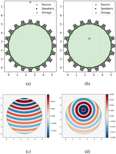
For the experiments we compare the performance of our method with the state-of-the-art methods WFS, NFC-HOA and L 2 -PMM in terms of its azimuth localization and coloration performance, as they are the main features of the auditory scene for spatial sound. We use Dietz's model to measure binaural azimuth localization [63] and McKenzie's model for binaural coloration [78]. The setup for the numerical experiments consists of an equispaced arrangement of 20 loudspeakers lying on a circle of radius 2.5 m and at π/ 4 ≈ 0 . 785 m from each other. The region of interest Ω is a concentric circle of radius 2.4975 m (Fig. 1). The speed of sound is c s = 343 m/s. Two instances of this setup were evaluated: the near-field instance , where the source outside the arrangement at 5 m of its center with ̂ c 0 ( f ) = 68 dB, and the focus-source instance , where the source is inside the arrangement at 0.82 m of its center (Fig. 1b) with ̂ c 0 ( f ) = 60 dB. In both cases, f = 343 Hz. To construct the perceptual maps D and L we assume that the listeners are looking at the virtual sound source, which implies that Θ = Θ( x ) = { ang ( x 0 -x ) } .
The SWEET-ReLU algorithm and the L 2 -PMM method were implemented in Python 3.8 using the CVXPY package, version 1.1.15 [91, 92] and MOSEK, version 9.3.6 [93]. The simulations of 2.5D NFC-HOA and 2.5D WFS were done with the Sound Field Synthesis Toolbox (SFST), version 3.2 [94], unless the focus-source 2.5D NFC-HOA simulations, which were done following the angular weighting approach [95]. The HRTFs used to simulate ¯ u and ¯ u 0 were constructed as the circulant Fourier transform of the elements of the TU-Berlin HRIR free data base [96]. Dietz's and McKenzie's models were implemented using Matlab 2022a with the Auditory Modelling Toolbox (AMT), version 1.1 [97].
For the implementation of the HRTFs, the 3 meters radial distance HRIRs of the data set were radially extrapolated using delay and attenuation, according to the map
<!-- formula-not-decoded -->
where d is the desired radial distance. It should be noticed that for short distances, e.g. less than 1 m, ILDs vary significantly with distance [96]. Hence, the experiments might be enhanced by using a complete HRTF data set. For the
Figure 1: Rows: Experimental setup. Target ̂ u 0 ( f ) (real part). Columns: Near-field instance. Focus-source instance.
<details>
<summary>Image 1 Details</summary>
### Visual Description
## Multi-Panel Chart: Wave Propagation Setups and Results
### Overview
This image presents a 2x2 grid of plots, labeled (a) through (d), illustrating two distinct wave propagation setups and their corresponding simulated wave patterns within a circular domain. The top row (a, b) depicts the spatial arrangement of a "Source" and "Speakers" relative to a domain labeled "Omega". The bottom row (c, d) displays heatmaps of wave amplitudes within the "Omega" domain, corresponding to the setups above them.
### Components/Axes
All four subplots share similar Cartesian coordinate systems.
- **X-axis:** Ranges from 0 to 5, with major ticks at 0, 1, 2, 3, 4, 5. No explicit label is provided for the X-axis.
- **Y-axis:**
* For subplots (a) and (b): Ranges from 0 to 7, with major ticks at 0, 1, 2, 3, 4, 5, 6, 7. No explicit label is provided for the Y-axis.
* For subplots (c) and (d): Ranges from 0 to 5, with major ticks at 0, 1, 2, 3, 4, 5. No explicit label is provided for the Y-axis.
**Legend (Common to subplots (a) and (b), located top-right):**
- `o` **Source**: Represented by a white circle with a black outline.
- `▲` **Speakers**: Represented by a solid black upward-pointing triangle.
- `•` **Omega**: Represented by a solid green circle.
**Color Bars (Specific to subplots (c) and (d), located on the right side of each plot):**
- **Subplot (c) Color Bar:**
* Range: -0.010 to 0.010.
* Major ticks: -0.010, -0.005, 0.000, 0.005, 0.010.
* Color gradient: Deep blue at -0.010, transitioning through light blue, white (around 0.000), light red, to deep red at 0.010.
- **Subplot (d) Color Bar:**
* Range: -0.020 to 0.020.
* Major ticks: -0.020, -0.015, -0.010, -0.005, 0.000, 0.005, 0.010, 0.015, 0.020.
* Color gradient: Deep blue at -0.020, transitioning through light blue, white (around 0.000), light red, to deep red at 0.020.
### Detailed Analysis
**Subplot (a): Setup with External Source**
- **Type:** Diagram/Scatter Plot.
- **Main Elements:**
* A large grey gear-like structure with 20 teeth is centrally positioned, spanning approximately x-coordinates 0 to 5 and y-coordinates 0 to 5. Its center is roughly at (2.5, 2.5).
* Inside the gear, a circular region, outlined in green, is densely filled with small green dots. This region represents "Omega" as per the legend. The "Omega" circle is centered at approximately (2.5, 2.5) with a radius of about 2.5 units.
* Twenty black triangles, representing "Speakers", are arranged in a circle along the inner circumference of the gear structure, precisely on the green outline of the "Omega" domain.
* A single white circle with a black outline, representing the "Source", is located significantly above the "Omega" domain, at approximately coordinates (2.5, 7.5).
- **Label:** (a) is positioned at the bottom-left of the subplot.
**Subplot (b): Setup with Internal Source**
- **Type:** Diagram/Scatter Plot.
- **Main Elements:**
* The grey gear-like structure, the green-outlined "Omega" domain filled with green dots, and the twenty black "Speakers" are identical in position and appearance to subplot (a).
* The "Source" (white circle with black outline) is positioned *inside* the "Omega" domain, slightly above its center, at approximately coordinates (2.5, 3.4).
- **Label:** (b) is positioned at the bottom-left of the subplot.
**Subplot (c): Wave Pattern for External Source Setup**
- **Type:** Heatmap/Contour Plot.
- **Main Elements:**
* A circular region, outlined in green, is displayed, matching the "Omega" domain from subplots (a) and (b) in size and position (centered at approximately (2.5, 2.5) with a radius of about 2.5 units).
* **Trend:** The heatmap shows a pattern of approximately 5-6 horizontal, parallel bands of alternating red and blue colors, separated by white regions. The bands are more intense (deeper red/blue) towards the top and bottom edges of the circle and fade towards the horizontal center line (y=2.5) where the colors are lighter or white. The pattern suggests a standing wave or a plane wave propagating vertically.
* **Values:** The color bar indicates values ranging from -0.010 (deep blue) to 0.010 (deep red), with white representing values near 0.000.
- **Label:** (c) is positioned at the bottom-left of the subplot.
**Subplot (d): Wave Pattern for Internal Source Setup**
- **Type:** Heatmap/Contour Plot.
- **Main Elements:**
* A circular region, outlined in green, is displayed, matching the "Omega" domain from subplots (a) and (b) in size and position (centered at approximately (2.5, 2.5) with a radius of about 2.5 units).
* **Trend:** The heatmap displays a pattern of concentric rings of alternating red and blue colors, separated by white regions. The center of these rings is located at approximately (2.5, 3.4), which corresponds precisely to the "Source" location in subplot (b). The intensity (color saturation) is highest at the center (deep red) and in the outer rings, decreasing towards the white rings. This pattern is characteristic of a radially propagating wave originating from a point source.
* **Values:** The color bar indicates values ranging from -0.020 (deep blue) to 0.020 (deep red), with white representing values near 0.000. The maximum amplitude in this plot is twice that of subplot (c).
- **Label:** (d) is positioned at the bottom-left of the subplot.
### Key Observations
- Subplots (a) and (b) illustrate two different source configurations for wave generation within the "Omega" domain, which is consistently a circular region surrounded by "Speakers" and a gear-like boundary.
- Subplot (a) places the "Source" externally, high above the "Omega" domain.
- Subplot (b) places the "Source" internally, within the "Omega" domain, slightly off-center.
- Subplot (c) shows a wave pattern with horizontal bands, suggesting a wave field influenced by an external or distant source, possibly generating a plane-wave-like behavior or a specific mode.
- Subplot (d) shows a wave pattern with concentric rings originating from the internal source location depicted in subplot (b), characteristic of a point source radiating waves.
- The maximum amplitude of the wave field in (d) (0.020) is twice that in (c) (0.010), suggesting a stronger or differently scaled wave generation for the internal source case.
- The "Speakers" are consistently positioned on the boundary of the "Omega" domain in both setups (a) and (b), implying they might be used to control or measure the wave field at the boundary.
### Interpretation
The image effectively demonstrates the impact of source location on wave propagation patterns within a confined circular domain. The "Omega" domain, filled with green dots, likely represents the computational or physical space where the wave equation is solved or observed. The "Speakers" on the boundary suggest an active control or measurement system, possibly for acoustic or electromagnetic waves, where the gear-like structure might represent a physical enclosure or an array of transducers.
Subplots (a) and (c) together suggest a scenario where an external "Source" (perhaps a distant plane wave source or a source whose effect is shaped by the "Speakers") generates a wave field that manifests as horizontal standing waves or modes within the "Omega" domain. The horizontal banding implies a dominant directionality or boundary condition effect.
Conversely, subplots (b) and (d) illustrate a classic point-source radiation scenario. When the "Source" is placed directly inside the "Omega" domain, the resulting wave pattern (d) clearly shows circular wavefronts emanating from that source. The higher amplitude in (d) compared to (c) could indicate a more direct coupling of energy from the internal source to the domain, or simply a different scaling factor in the simulation/measurement.
The consistent presence of the "Speakers" on the boundary of "Omega" in both setups implies their role is independent of the source's primary location (internal vs. external). They could be acting as sensors, actuators for active noise control, or simply defining the boundary conditions for the wave propagation. The overall presentation suggests a study of wave phenomena in a bounded region, exploring different excitation methods and their resulting field distributions.
</details>
implementation of Dietz's model, since we treated (pseudo) sinusoidal signals, the interaural phase differences (IPDs) and ILDs of the reproduced signals were extracted manually following the convention of [63] as
<!-- formula-not-decoded -->
<!-- formula-not-decoded -->
<!-- formula-not-decoded -->
Then, the unwrapped ITDs were obtained from the ILDs and IPDs using the dietz2011\_unwrapitd.mat function. The estimated azimuth localization is obtained by plugging the ITDs into the itd2angle.mat function, which uses the itd2angle\_lookuptable.mat table. The latter table is constructed with the same HRTFs that we consider for the simulation of ¯ u and ¯ u 0 . For the implementation of McKenzie's model, the binaural signals were transformed to time-domain using a sampling frequency of 44100 Hz and a number of samples of 256. As proposed in [98, Chapter 5.6.2], the implementation of the angular weighting for NFC-HOA in focus-source instances was defined, for the n -th mode, as
<!-- formula-not-decoded -->
where d is the distance from the source to the center of the room, and ω = 2 πf . For the implementation of the SWEET method, we have chosen ε i adaptively with percentile p = 99 . For SWEET and L 2 -PMM a uniform discretization of 2348 points was used for Ω at a distance of at most 0.09 m, achieving more than 30 points per wavelength.
To compare the performance of the methods, we measure the size of the localization sweet spot (LSS) and coloration sweet spot (CSS). We former is the region where the perceived azimuth localization measured by Dietz's model deviates no more than 5 degrees from the desired one, whereas the latter is the region where the coloration measured by McKenzie's model is lower or equal than 13 sones. As discussed in [78], a coloration lower than 13 sones is strongly correlated with empirical MUSHRA tests with more than 80 out of 100 points. It should be noted that, since we analyse (pseudo) sinusoidal signals of frequency 343 Hz, in these experiments the CSS and LSS are constituted by the points where the interaural amplitude or phase (respectively) of the binaural signal are correctly reconstructed.
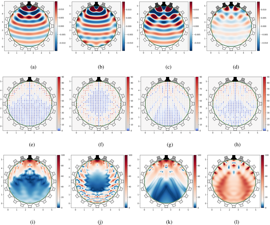
Figure 2: Near-field instance. Rows: Near-field ̂ u ( f ) (real part). Dietz's near-field azimuth localization, where the direction of the arrows represent the perceived localization whereas the color represents the deviation in degrees of the perceived localization from the desired one. McKenzie's near-field coloration (sones). Columns: SWEET-ReLU, NFC-HOA, WFS, and L 2 -PMM.
<details>
<summary>Image 2 Details</summary>
### Visual Description
## Grid of Acoustic Field Visualizations
### Overview
The image displays a 12-panel grid of scientific visualizations, arranged in 3 rows and 4 columns, labeled (a) through (l). Each panel depicts a physical field within a circular domain, approximately 5 units in diameter, with a series of 16 grey rectangular elements (likely transducers or sensors) and a larger black irregular shape positioned along the top edge of the circle. The plots in the first row (a-d) are scalar field contour plots with a bipolar color scale. The plots in the second row (e-h) are vector field plots overlaid on a scalar field, using a unipolar color scale. The plots in the third row (i-l) are scalar field contour plots, also using a unipolar color scale.
### Components/Axes
* **Overall Structure**: The image is a 3x4 grid of subplots, labeled (a) through (l) from left to right, top to bottom, centered below each plot.
* **Domain**: Each subplot features a circular domain, outlined in green, approximately centered within the plot area. The domain spans roughly from x=0 to x=5 and y=0 to y=5.
* **Transducers/Sensors**: Along the top edge of the circular domain, there is a black, irregular, somewhat jagged shape, and 16 distinct grey rectangular elements arranged in an arc. These elements are consistently present across all 12 subplots.
* **X-axis**: For all subplots, the horizontal axis is labeled from 0 to 5, with major ticks at 0, 1, 2, 3, 4, 5.
* **Y-axis**: For all subplots, the vertical axis is labeled from 0 to 5, with major ticks at 0, 1, 2, 3, 4, 5.
* **Color Legends**: Each subplot has a vertical color bar (legend) positioned on its right side, indicating the mapping of colors to numerical values.
### Detailed Analysis
#### Row 1: Scalar Field Contour Plots (a-d)
These plots visualize a scalar field with both positive and negative values.
* **Color Legend**: Ranges from -0.010 (dark blue) at the bottom to 0.010 (dark red) at the top. The midpoint, 0.000, is represented by a light beige/white color. Intermediate ticks are at -0.005 and 0.005.
* **(a)**: Shows horizontal wave-like patterns. Strong positive values (red) are observed in bands around y=4.0 and y=2.5. Strong negative values (blue) are in bands around y=3.2 and y=1.5. The pattern is largely symmetrical across the vertical midline.
* **(b)**: Similar horizontal wave patterns to (a), but with a slight vertical shift or phase difference. Strong positive values (red) are prominent around y=4.5 and y=2.8. Strong negative values (blue) are around y=3.5 and y=1.8.
* **(c)**: Displays a more complex, localized pattern. A strong red region is near the top-center (y~4.5). Two smaller, distinct red regions are located symmetrically around y=2.5, at x~1.5 and x~3.5. Blue regions are more concentrated in the lower half, forming a "W" or "M" shape, with strong negative values around y=1.0-2.0.
* **(d)**: Features a pattern with a central red region near y=4.0, flanked by blue regions, then red regions, then blue regions towards the bottom. The patterns are more concentrated and less uniform than (a) and (b), showing distinct lobes of positive and negative values.
#### Row 2: Vector Field Plots (e-h)
These plots visualize a vector field, with arrows indicating direction, overlaid on a scalar field represented by color.
* **Color Legend**: Ranges from 0 (dark blue) at the bottom to 90 (dark red) at the top. Intermediate ticks are at 10, 20, 30, 40, 50, 60, 70, 80. This scale likely represents the magnitude of the vectors or an associated scalar quantity.
* **(e)**: Vectors predominantly point downwards. The upper half of the circular domain shows lighter colors (yellow/orange, values ~50-70), indicating higher scalar values, with dense downward-pointing vectors. The lower half is darker blue (values ~10-30), with less dense or shorter downward-pointing vectors.
* **(f)**: Similar to (e), vectors generally point downwards. The region of higher scalar values (reddish, ~50-70) is more concentrated towards the top-center, forming a "V" or inverted "U" shape. The lower region remains darker blue (lower values).
* **(g)**: Vectors generally point downwards, exhibiting a clear divergence pattern. Vectors near the top-center point straight down. Vectors towards the sides point downwards and slightly inwards. The scalar field shows a central dark blue (low value) region extending downwards, flanked by lighter blue/red (higher value) regions.
* **(h)**: Vectors generally point downwards, with a more pronounced inward curvature towards the bottom compared to (g). The scalar field shows a central dark blue (low value) region extending downwards, similar to (g), but the higher value regions are more spread out laterally.
#### Row 3: Scalar Field Contour Plots (i-l)
These plots visualize a scalar field with only positive values.
* **Color Legend**: Ranges from 0 (dark blue) at the bottom to 100 (dark red) at the top. Intermediate ticks are at 20, 40, 60, 80.
* **(i)**: Shows a strong blue (low value) region in the lower half of the domain, forming a broad "U" shape opening upwards. The upper half, particularly near the transducers, shows red (high value) regions.
* **(j)**: Displays a complex, intricate pattern. A central blue (low value) region forms an irregular "blob" in the middle-lower part of the domain. Red (high value) regions are concentrated near the transducers and form complex, swirling patterns around the central blue region.
* **(k)**: Features a distinct "V" shape of dark blue (low values) originating from the top-center and extending downwards towards the bottom of the circle. The regions outside this "V" are predominantly red (high values), especially near the transducers and along the sides of the "V".
* **(l)**: Shows a dominant red (high value) region covering most of the domain, particularly the lower half, forming a broad "U" shape. Blue (low value) regions are concentrated near the transducers and form thin, intricate patterns around the edges of the red regions, especially in the upper half.
### Key Observations
* The circular domain and the transducer-like elements at the top suggest these plots represent physical fields (e.g., acoustic, electromagnetic) within a confined space.
* The first row (a-d) shows oscillating fields (positive and negative values), characteristic of wave amplitudes or potentials. The patterns evolve from more uniform horizontal waves to more complex, localized interference patterns.
* The second row (e-h) visualizes vector fields, likely representing flux or velocity, with a general downward propagation from the transducer region. The scalar background in this row seems to represent the magnitude of this field or a related quantity.
* The third row (i-l) shows fields with only positive values, possibly representing intensity, power, or squared amplitude. These plots demonstrate various focusing and spreading patterns, including broad low-intensity regions (i), complex distributions (j), a highly focused low-intensity beam (k), and a broad high-intensity region (l).
* The progression across columns (a-d, e-h, i-l) indicates a systematic change in the field patterns, which could correspond to different excitation modes, frequencies, or time steps of the transducers.
### Interpretation
The collection of plots likely illustrates different aspects of wave propagation or field distribution generated by an array of transducers positioned at the top of a circular medium.
* **Wave Phenomena**: The bipolar nature of the first row (a-d) strongly suggests the visualization of wave amplitudes (e.g., pressure, displacement). The transition from relatively simple, horizontal wavefronts in (a) and (b) to more complex, localized patterns in (c) and (d) could represent different modes of excitation, interference patterns from multiple sources, or snapshots of a propagating wave at different times.
* **Energy/Flux Distribution**: The vector fields in the second row (e-h) likely represent the direction and magnitude of energy flow or particle velocity within the medium. The consistent downward direction of the vectors indicates that the transducers are acting as sources, directing energy into the circular domain. The variations in vector density and underlying scalar field (color) suggest different beamforming or focusing capabilities. For instance, (g) and (h) show patterns indicative of a more focused or channeled energy propagation.
* **Intensity/Power Maps**: The unipolar scalar fields in the third row (i-l) are consistent with visualizations of wave intensity or power, which are always non-negative. These plots demonstrate the spatial distribution of energy. Plot (k), with its distinct "V" shape of low intensity, strongly suggests a focused "null" or region of destructive interference, while the surrounding red areas indicate high intensity. Conversely, (l) shows a broad region of high intensity, possibly a wide beam or diffuse field. These variations highlight the ability to control the spatial distribution of energy within the medium using the transducer array.
In summary, the images provide a comprehensive view of how an array of transducers can generate and shape various physical fields within a circular domain, showcasing wave amplitudes, energy flow, and intensity distributions under different operational conditions or modes. The green circle defines the boundary of the medium, which likely influences the observed wave patterns through reflection or absorption.
</details>
The CSS and LSS generated by each method for the near-field and focus-source instances are shown in Fig. 2 and 3 respectively, and their size is shown in Table 1. The blue zones of Figs 2e-l, Figs 3e-l represent the sweet spots of each case. The estimated localization in Figs 2e-h, Figs 3e-h is shown for deviations of 0 to 90 degrees from the desired one. Greater deviations are represented by a dot with no direction.
| | SWEET | NFC-HOA | WFS | L 2 -PMM |
|-------------|---------|-----------|-------|------------|
| NF CSS | 70.8% | 51% | 55.6% | 3.3% |
| NF LSS | 68.4% | 42.9% | 47.9% | 52.3% |
| FS CSS | 58.7% | 27.8% | 0.1% | 5.2% |
| FS LSS | 54% | 42.9% | 16.2% | 40.1% |
| FS LSS (DH) | 50.8% | 37.8% | 12.5% | 28.9% |
Table 1: CSS and LSS over Ω fractions in Near-field (NF) and Focus-Source (FS)] instances. [(DH) disregards the convergent halfspace].
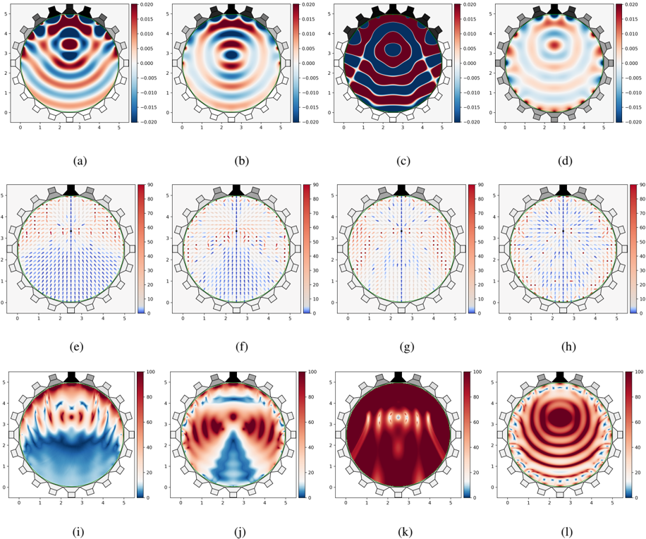
Figure 3: Focus-source instance. Rows: Near-field ̂ u ( f ) (real part). Dietz's near-field azimuth localization, where the direction of the arrows represent the perceived localization whereas the color represents the deviation in degrees of the perceived localization from the desired one. McKenzie's near-field coloration (sones). Columns: SWEET-ReLU, NFC-HOA, WFS, and L 2 -PMM.
<details>
<summary>Image 3 Details</summary>
### Visual Description
## Multi-Panel Field Visualizations in a Circular Domain
### Overview
This image presents a grid of twelve sub-plots, arranged in three rows and four columns, labeled (a) through (l). Each sub-plot visualizes a field within a circular domain, which is outlined in green. Surrounding this circular domain are 18 external elements, likely transducers or sensors: two black trapezoidal shapes positioned at the top-center, and 16 grey trapezoidal shapes distributed around the remaining circumference. The plots are broadly categorized into three types based on their colorbar ranges and visual elements: scalar fields with signed values (a-d), scalar fields with superimposed vector fields (e-h), and scalar fields with non-negative values (i-l).
### Components/Axes
All sub-plots share common structural elements:
* **X-axis**: Labeled with numerical markers 0, 1, 2, 3, 4, 5, extending horizontally across the bottom of each circular domain.
* **Y-axis**: Labeled with numerical markers 1, 2, 3, 4, 5, extending vertically along the left side of each circular domain.
* **Circular Domain**: An inner region bounded by a thin green circular line, representing the area where the fields are visualized.
* **External Elements**: 18 trapezoidal shapes are arranged around the outer edge of the circular domain. Two of these are colored black and are positioned at the very top, centered above the circular domain. The remaining 16 are grey and are evenly distributed around the rest of the circumference.
* **Sub-plot Labels**: Each sub-plot is labeled with a lowercase letter in parentheses, positioned below its respective plot (e.g., (a), (b), (c), etc.).
* **Colorbars/Legends**: Each group of four sub-plots (rows) shares a common vertical colorbar on its right side, indicating the range of values represented by the colors.
**Colorbar Details:**
* **Plots (a) - (d)**:
* Range: -0.020 (dark blue) to 0.020 (dark red).
* Markers: -0.020, -0.015, -0.010, -0.005, 0.000 (white/light blue), 0.005, 0.010, 0.015, 0.020.
* **Plots (e) - (h)**:
* Range: 10 (dark blue) to 90 (dark red).
* Markers: 10, 20, 30, 40, 50, 60, 70, 80, 90.
* **Plots (i) - (l)**:
* Range: 0 (dark blue) to 100 (dark red).
* Markers: 0, 20, 40, 60, 80, 100.
### Detailed Analysis
#### Scalar Fields with Signed Values (Plots a-d)
These plots use a diverging color scheme where blue represents negative values, red represents positive values, and white/light blue represents values near zero.
* **(a)**:
* **Trend**: Displays a complex wave pattern with diagonal symmetry. A horizontal blue band (negative values, approximately -0.010 to -0.015) is prominent around the y=3 level. Two distinct red lobes (positive values, approximately 0.010 to 0.015) are visible in the top-left and bottom-right quadrants, while two blue lobes (negative values, approximately -0.010 to -0.015) are in the top-right and bottom-left quadrants.
* **Values**: Peaks around ±0.015.
* **(b)**:
* **Trend**: Shows a clear concentric circular wave pattern. A central red circle (positive values, approximately 0.010 to 0.015) is surrounded by a blue ring (negative values, approximately -0.010 to -0.015), which is then enclosed by another red ring (positive values, approximately 0.005 to 0.010). The intensity generally decreases towards the outer edge.
* **Values**: Peaks around ±0.015.
* **(c)**:
* **Trend**: Exhibits a pattern of alternating vertical stripes. A strong central vertical blue band (negative values, approximately -0.015 to -0.020) is flanked by two dark red bands (positive values, approximately 0.015 to 0.020). Further out, blue bands appear. The pattern is symmetric about the vertical axis.
* **Values**: Peaks around ±0.020.
* **(d)**:
* **Trend**: Features a central red region (positive values, approximately 0.005 to 0.010), surrounded by an inner blue ring (negative values, approximately -0.005 to -0.010). The outer region displays a more complex arrangement of alternating red and blue lobes, suggesting a combination of radial and angular variations.
* **Values**: Peaks around ±0.010.
#### Scalar Fields with Vector Fields (Plots e-h)
These plots combine a heatmap with a sequential color scheme (blue for lower values, red for higher values) and superimposed blue arrows representing a vector field.
* **(e)**:
* **Heatmap Trend**: The top half of the circular domain (above y~3) is predominantly red (higher values, approximately 60-80), while the bottom half is predominantly blue (lower values, approximately 10-30). A horizontal transition zone is visible around y=3.
* **Vector Field Trend**: Blue arrows in the top half generally point downwards and slightly inwards towards the center. Arrows in the bottom half generally point upwards and slightly outwards. This indicates a flow pattern diverging from the bottom and converging towards the top, or vice-versa.
* **(f)**:
* **Heatmap Trend**: Similar to (e), with the top half red (approximately 60-80) and the bottom half blue (approximately 10-30). The horizontal transition appears slightly more defined.
* **Vector Field Trend**: The arrow pattern is very similar to (e), with downward-inward flow in the top and upward-outward flow in the bottom.
* **(g)**:
* **Heatmap Trend**: Again, the top half is red (approximately 60-80) and the bottom half is blue (approximately 10-30). The transition zone shows some central red extension downwards.
* **Vector Field Trend**: The arrow pattern is consistent with (e) and (f), showing a similar flow.
* **(h)**:
* **Heatmap Trend**: The top half is red (approximately 60-80) and the bottom half is blue (approximately 10-30). The transition appears smoother than in previous plots in this row.
* **Vector Field Trend**: The arrow pattern remains consistent with (e), (f), and (g), indicating a stable flow characteristic across these variations.
#### Scalar Fields with Non-Negative Values (Plots i-l)
These plots use a sequential color scheme where dark blue represents zero or very low values, and dark red represents the highest values.
* **(i)**:
* **Trend**: Features a strong red region (high values, approximately 80-100) in the top half, with complex, finger-like wave patterns extending downwards into the predominantly blue (low values, approximately 0-20) bottom half.
* **Values**: Ranges from 0 to 100.
* **(j)**:
* **Trend**: Shows a strong red region (high values, approximately 80-100) in the top half. A prominent V-shaped blue region (low values, approximately 0-20) extends upwards from the bottom-center, creating a distinct pattern symmetric about the vertical axis. The regions flanking the blue V-shape are red (approximately 60-80).
* **Values**: Ranges from 0 to 100.
* **(k)**:
* **Trend**: Characterized by highly concentrated red regions (high values, approximately 80-100) in the top half, forming multiple distinct lobes or "fingers" extending downwards. The entire circular domain is largely dominated by red, indicating high values throughout (approximately 60-100), with very little blue.
* **Values**: Predominantly high, ranging from 60 to 100.
* **(l)**:
* **Trend**: Displays a very clear and intense concentric circular wave pattern, similar to (b) but with non-negative values. A central intense red circle (high values, approximately 80-100) is surrounded by a dark blue ring (low values, approximately 0-20), followed by another intense red ring, and so on. The pattern shows distinct oscillations between high and low values.
* **Values**: Oscillates between 0-20 and 80-100.
### Key Observations
* **Consistent Setup**: All 12 plots share the same circular domain, axis ranges, and external transducer arrangement, suggesting they represent different states or measurements within the same system.
* **Distinct Field Types**: The three rows clearly differentiate between signed scalar fields, vector fields superimposed on scalar fields, and non-negative scalar fields, likely representing different physical quantities (e.g., pressure, velocity, intensity).
* **Symmetry and Patterns**: Many plots exhibit clear symmetry (e.g., (b), (c), (j), (l) show vertical or radial symmetry). Patterns range from simple concentric circles (b, l) to vertical stripes (c) and complex wave-like structures (a, i).
* **Directional Flow**: The vector fields (e-h) consistently show a flow pattern originating from the bottom and moving towards the top, or vice-versa, with a strong influence from the top-center region where the black transducers are located.
* **Energy Localization**: Plots (i-l) show regions of high energy (intense red) which are often localized or concentrated, particularly in the upper half of the domain.
### Interpretation
These visualizations likely represent acoustic or wave fields within a circular resonator or medium, possibly a fluid-filled cavity or a solid disk. The external trapezoidal elements are almost certainly transducers, with the two black ones at the top potentially acting as primary sources or receivers, given their distinct color and the observed field patterns.
* **Plots (a)-(d)**, with their signed values, could represent **acoustic pressure fields** or displacement fields, where positive and negative values indicate compression and rarefaction, or displacement in opposite directions. The variations between these plots might correspond to different resonant modes or excitation frequencies. For instance, (b) and (l) suggest radial modes, while (c) suggests a standing wave pattern.
* **Plots (e)-(h)**, combining a scalar field with a vector field, most likely depict **particle velocity fields** (vectors) superimposed on a scalar quantity like acoustic intensity or energy density. The consistent downward-inward/upward-outward flow in the vector fields, especially originating from the top, strongly suggests that the black transducers are acting as sources, driving the medium. The scalar field in these plots (red at top, blue at bottom) could represent the magnitude of the velocity or a related energy metric, indicating higher activity near the source.
* **Plots (i)-(l)**, with their non-negative values, are highly indicative of **acoustic intensity** or **energy density** fields. These quantities are always positive and represent the power flow or energy stored in the medium. The intense red regions highlight areas of high energy concentration. The concentric patterns in (l) further support the idea of wave propagation and energy distribution.
The overall set of plots provides a comprehensive view of how different physical quantities (pressure, velocity, intensity) behave under various conditions or modes within the circular domain, likely influenced by the specific arrangement and activation of the external transducers. The differences between the plots in each row could represent different excitation signals, frequencies, or phases, demonstrating the versatility of the system in generating diverse field patterns. The consistent flow in (e)-(h) points to a directional energy transfer, possibly for applications like focused ultrasound or acoustic manipulation.
</details>
For the near-field instance, both the LSS and CSS generated by our method are more than 20 and 10 points (respectively) larger than that generated by any other method. The LSS and CSS generated by NFC-HOA (Figs. 2j, 2f) are centered, whereas that generated by WFS (Figs. 2k, 2g) are localized farther away from the source. This is correlated with their degradation of the sound field, which is consistent with the analysis in [14]. Moreover, their LSS are consistent with the empirical results exposed in [34]: the perceived localization for NFC-HOA degrades away from the center, whereas for WFS the perceived localization is fairly good over almost all the listening region. However, we believe that the perceived localization for WFS and NFC-HOA behaves slightly worse here than in [34] because we analyze sinusoidal signals instead of Gaussian white noise, which has uniform spectral content. In contrast, the LSS and CSS generated by our method (Figs. 2i, 2e) behave like those generated by WFS, but almost encompasses those generated by NFC-HOA. The LSS of L 2 -PMM (Fig. 2h) is larger than that of WFS and NFC-HOA, but its CSS (Fig. 2l) is almost negligible. This is consistent with the sound wave u produced with L 2 -PMM (Fig. 2d) as the spatial phase of the signals is fairly well reconstructed, whereas its amplitude is too small.
In the focus-source instance, due to reasons of causality, theoretically any method can achieve the correct reproduction of the direction of propagation of u 0 in one half-space defined by { x i } n s i =0 , where the sound field diverges from the focus-source position [99]. In the other half-space the reproduced wave field converges towards the location of the virtual source. As shown in Figs. 3e-h, the LSS of all the methods comprise a portion of the converging part of the
sound field. This is possible because the interaural phase of the binaural sinusoidal signals is correctly recreated at those points. However, we believe that in more complex scenarios, involving multi-frequency signals and allowing the listener to turn her head, e.g., considering a larger Θ , it would not be possible to recreate correctly and consistently the localization illusion. As shown in [98, Chapter 5.6] 'for listeners located in the converging part of the sound field, the perception is unpredictable since the interaural cues are either contradictory or change in a contradictory way when the listener moves the head. ' Table 1 contains the fraction of the LSS over Ω for the focus-source instance considering all the points of the converging half-space as incorrectly reconstructed, denoted by the label (DH).
For the focus-source instance, the LSS and CSS generated by our method (Fig. 3e, 3i) is approximately 10 and 30 (respectively) points larger than those generated by other methods. The LSS and CSS generated by NFC-HOA (Fig. 3f, 3j) is concentrated in a limited region at the diverging part and around a vertical line that passes through x 0 . The LSS generated by WFS (Fig. 3g) is almost contained in the same vertical line, although the error in the localization reconstruction is below 15 degrees in a larger area. The CSS generated by WFS (Fig. 3k) is almost empty as the resulting u has a large amplitude. This suggest that a focus-source formulation for WFS needs a factor for amplitude normalization. The LSS of L 2 -PMM (Fig. 3h) has almost the same size as that of NFC-HOA, but its CSS (Fig. 2l) is almost negligible. This is consistent with the sound wave u produced with L 2 -PMM (Fig. 3d) as the spatial phase of the signals is fairly well reconstructed, whereas its amplitude is too small. The LSS and CSS generated by our method (Fig. 3e, 3i) comprises almost all the divergent part. This highlights one of the advantages of the greedy approach of SWEET-ReLU: it is capable to detect the direction of u 0 over Ω in its first iterations, to then prioritize the part of Ω where a good fit to ¯ u 0 can be obtained. This is a possible explanation for the amplitude mismatch of L 2 -PMM both in the near-field (Fig. 2d) and the focus-source (Fig. 3d) instances: just minimizing the square of the spatial errors strongly penalizes the spatial points where the amplitude is very large and difficult to reconstruct, i.e., near the loudspeakers. Then, L 2 -PMM finds a solution where the amplitude error at those points is not too large, leading to a small overall amplitude.
## 7 Discussion
Our results show the SWEET-ReLU method yields state-of-the-art results in standard numerical experiments with our proof-of-concept implementation. We believe the performance in these experiments is representative of what we would observe when using more complex pyscho-acoustic models for the perceptual dissimilarity and the loudness discomfort. A key component of our method is the perceptual dissimilarity D . Although its form in our proof-of-concept implementation is quite flexible, it does not account for spatialization and other binaural effects. Finding a model to account for these effects such that D satisfies (5) is the subject of future research. It should be noted that, as it is shown in [100], the overall quality of a spatial sound system can be explained to 70% by coloration or timbral fidelity, which can be partially characterized by monoaural effects, and 30% by spatial fidelity, which needs to be characterized by binaural effects.
Furthermore, our proof-of-concept experiments show that even though the perceptual model we use is an extension of a monoaural model using a worst-case approach, it still is able to perform better than state-of-the-art methods in terms of localization and coloration. This suggests our implementation with this model is able to capture correctly some of the spatial properties of the auditory scene, even though these properties are not explicitly in the model. This might be explained because the coloration and localization is strongly dependant of the amplitude and phase of the binaural signals, which are controlled by our implementation of a binaural extension of an amplitude and phase-sensitive monaural model.
Although our implementation assumes the loudspeakers and the sources are monopoles, we believe our method can be readily implemented in real settings with non-trivial sound sources. For instance, reverberation, different radiation patterns for the loudspeakers, and other time-invariant effects can be incorporated by modifying the Green function G k in (2) and the transfer functions in (4) accordingly.
Finally, although we have not fully developed a theory for the convergence of SWEET-ReLU, our numerical experiments show that the method converges to reasonable results in practice. Furthermore, our proof-of-concept implementation avoids any potential issues arising from the discretization of the models, either due to numerical computation of the Green function or transfer functions, or to the discretization of the integral that defines the weighted area. Further analysis about this point will be the subject of future work.
## 8 Conclusion
In this work, we introduced a theoretical framework for spatial audio perception that allows the definition of a perceptual sweet spot, that is, the region where the spatial auditory illusion is achieved when approximating one sound wave by another. Furthermore, we developed a method that finds an approximating sound wave that maximizes this sweet spot while guaranteeing no loudness discomfort over a spatial region of interest. We provided a theoretical analysis of the method, and an efficient algorithm, the SWEET-ReLU algorithm, for its numerical implementation. In a proofof-concept implementation using monopoles emitting (pseudo) sinusoidal signals, our method successfully captures some of the spatial properties of the auditory scene, such as localization and coloration, even though these properties are not explicitly in the model. We believe our method is a first step towards a novel approach for spatial sound with loudspeakers, bridging a gap between methods based on perceptual principles, and sound field synthesis methods.
## Acknowledgment
C. A. SL. was partially funded by ANID - FONDECYT - 1211643, ANID - Millennium Science Initiative Program -NCN17\_059 and ANID - Millennium Science Initiative Program - NCN17\_129.
## References
- [1] Rozenn Nicol. Creating auditory illusions with spatial-audio technologies. In The Technology of Binaural Understanding , pages 581-622. Springer, 2020.
- [2] Hagen Wierstorf, Alexander Raake, and Sascha Spors. Binaural assessment of multichannel reproduction. In The technology of binaural listening , pages 255-278. Springer, 2013.
- [3] Jens Blauert. Spatial hearing: the psychophysics of human sound localization . MIT press, 1997.
- [4] Sascha Spors, Hagen Wierstorf, Alexander Raake, Frank Melchior, Matthias Frank, and Franz Zotter. Spatial sound with loudspeakers and its perception: A review of the current state. Proceedings of the IEEE , 101(9):19201938, 2013.
- [5] DMLeakey. Some measurements on the effects of interchannel intensity and time differences in two channel sound systems. The Journal of the Acoustical Society of America , 31(7):977-986, 1959.
- [6] Hagen Wierstorf. Perceptual assessment of sound field synthesis . PhD thesis, 2014.
- [7] Matthias Frank and Franz Zotter. Exploring the perceptual sweet area in ambisonics. Journal of the Audio Engineering Society , may 2017.
- [8] Francis Rumsey. Surround sound. In In Immersive Sound: The Art and Science of Binaural and Multi-Channel Audio , page Chap. 6. Focal Press, 2017.
- [9] Ville Pulkki. Virtual sound source positioning using vector base amplitude panning. Journal of the Audio Engineering sSciety , 45(6):456-466, 1997.
- [10] Ville Pulkki. Coloration of amplitude-panned virtual sources. In Audio Engineering Society Convention 110 . Audio Engineering Society, 2001.
- [11] Christiaan Huygens. Traité de la lumière . Pierre Vander Aa Marchand Libraire, 1690.
- [12] Jérôme Daniel. Représentation de champs acoustiques, application à la transmission et à la reproduction de scènes sonores complexes dans un contexte multimédia . PhD thesis, University of Paris VI, 2000.
- [13] Michael A Gerzon. Periphony: With-height sound reproduction. Journal of the Audio Engineering Society , 21(1):2-10, 1973.
- [14] Jérôme Daniel, Sebastien Moreau, and Rozenn Nicol. Further investigations of high-order ambisonics and wavefield synthesis for holophonic sound imaging. In Audio Engineering Society Convention 114 . Audio Engineering Society, 2003.
- [15] Darren B Ward and Thushara D Abhayapala. Reproduction of a plane-wave sound field using an array of loudspeakers. IEEE/ACM Transactions on Audio Speech and Language Processing , 9, 2001.
- [16] Natsuki Ueno, Shoichi Koyama, and Hiroshi Saruwatari. Three-dimensional sound field reproduction based on weighted mode-matching method. IEEE/ACM Transactions on Audio Speech and Language Processing , 27:1852-1867, 12 2019.
- [17] Huanyu Zuo, Thushara D. Abhayapala, and Prasanga N. Samarasinghe. Particle velocity assisted three dimensional sound field reproduction using a modal-domain approach. IEEE/ACM Transactions on Audio Speech and Language Processing , 28:2119-2133, 2020.
- [18] Huanyu Zuo, Thushara D Abhayapala, and Prasanga N Samarasinghe. 3d multizone soundfield reproduction in a reverberant environment using intensity matching method. In ICASSP 2021-2021 IEEE International Conference on Acoustics, Speech and Signal Processing (ICASSP) , pages 416-420. IEEE, 2021.
- [19] Ole Kirkeby and Philip A Nelson. Reproduction of plane wave sound fields. The Journal of the Acoustical Society of America , 94(5):2992-3000, 1993.
- [20] Philippe-Aubert Gauthier, Alain Berry, and Wieslaw Woszczyk. Sound-field reproduction in-room using optimal control techniques: Simulations in the frequency domain. The Journal of the Acoustical Society of America , 117:662-678, 2 2005.
- [21] P.-A. Gauthier, P. Lecomte, and A. Berry. Source sparsity control of sound field reproduction using the elastic-net and the lasso minimizers. The Journal of the Acoustical Society of America , 141:2315-2326, 4 2017.
- [22] Maoshen Jia, Jiaming Zhang, Yuxuan Wu, and Jing Wang. Sound field reproduction via the alternating direction method of multipliers based lasso plus regularized least-square. IEEE Access , 6:54550-54563, 9 2018.
- [23] Qipeng Feng, Feiran Yang, and Jun Yang. Time-domain sound field reproduction using the group lasso. The Journal of the Acoustical Society of America , 143:EL55-EL60, 2 2018.
- [24] Nasim Radmanesh and Ian S. Burnett. Generation of isolated wideband sound fields using a combined two-stage lasso-ls algorithm. IEEE Transactions on Audio, Speech and Language Processing , 21:378-387, 2013.
- [25] Georgios N. Lilis, Daniele Angelosante, and Georgios B. Giannakis. Sound field reproduction using the lasso. IEEE Transactions on Audio, Speech and Language Processing , 18:1902-1912, 2010.
- [26] Thibaut Ajdler, Luciano Sbaiz, and Martin Vetterli. The plenacoustic function and its sampling. IEEE transactions on Signal Processing , 54(10):3790-3804, 2006.
- [27] Mihailo Kolundzija, Christof Faller, and Martin Vetterli. Sound field reconstruction: An improved approach for wave field synthesis. In Audio Engineering Society Convention 126 . Audio Engineering Society, 2009.
- [28] Michael Buerger, Roland Maas, Heinrich W Löllmann, and Walter Kellermann. Multizone sound field synthesis based on the joint optimization of the sound pressure and particle velocity vector on closed contours. In 2015 IEEE Workshop on Applications of Signal Processing to Audio and Acoustics (WASPAA) , pages 1-5. IEEE, 2015.
- [29] Michael Buerger, Christian Hofmann, and Walter Kellermann. Broadband multizone sound rendering by jointly optimizing the sound pressure and particle velocity. The Journal of the Acoustical Society of America , 143(3):1477-1490, 2018.
- [30] Mincheol Shin, Philip A. Nelson, Filippo M. Fazi, and Jeongil Seo. Velocity controlled sound field reproduction by non-uniformly spaced loudspeakers. Journal of Sound and Vibration , 370:444-464, 5 2016.
- [31] Augustinus J Berkhout, Diemer de Vries, and Peter Vogel. Acoustic control by wave field synthesis. The Journal of the Acoustical Society of America , 93(5):2764-2778, 1993.
- [32] EWStuart. Application of curved arrays in wave field synthesis. In Audio Engineering Society Convention 100 . Audio Engineering Society, 1996.
- [33] Sascha Spors, Rudolf Rabenstein, and Jens Ahrens. The theory of wave field synthesis revisited. In In 124th Convention of the AES . Citeseer, 2008.
- [34] Hagen Wierstorf, Alexander Raake, and Sascha Spors. Assessing localization accuracy in sound field synthesis. The Journal of the Acoustical Society of America , 141(2):1111-1119, 2017.
- [35] Hagen Wierstorf, Christoph Hohnerlein, Sascha Spors, and Alexander Raake. Coloration in wave field synthesis. In Audio Engineering Society Conference: 55th International Conference: Spatial Audio . Audio Engineering Society, 2014.
- [36] Sascha Spors and Jens Ahrens. A comparison of wave field synthesis and higher-order ambisonics with respect to physical properties and spatial sampling. In Audio Engineering Society Convention 125 . Audio Engineering Society, 2008.
- [37] Filippo M Fazi, Philip A Nelson, and Roland Potthast. Analogies and differences between three methods for sound field reproduction. Relation , 10:3, 2009.
- [38] Andreas Franck, Wenwu Wang, and Filippo Maria Fazi. Sparse 1-optimal multiloudspeaker panning and its relation to vector base amplitude panning. IEEE/ACM TRANSACTIONS ON AUDIO, SPEECH, AND LANGUAGE PROCESSING , 25, 2017.
- [39] Gergely Firtha, Péter Fiala, Frank Schultz, and Sascha Spors. On the general relation of wave field synthesis and spectral division method for linear arrays. IEEE/ACM Transactions on Audio Speech and Language Processing , 26:2393-2403, 12 2018.
- [40] Filippo Maria Fazi and Philip A. Nelson. A theoretical study of sound field reconstruction techniques. In 19th International Congress on Acoustics , September 2007.
- [41] James D Johnston and Yin Hay Vicky Lam. Perceptual soundfield reconstruction. In Audio Engineering Society Convention 109 . Audio Engineering Society, 2000.
- [42] Enzo De Sena, Huseyin Hacihabiboglu, and Zoran Cvetkovic. Analysis and design of multichannel systems for perceptual sound field reconstruction. IEEE Transactions on Audio, Speech and Language Processing , 21:1653-1665, 2013.
- [43] Tim Ziemer and Rolf Bader. Psychoacoustic sound field synthesis for musical instrument radiation characteristics. AES: Journal of the Audio Engineering Society , 65:482-496, 6 2017.
- [44] Ruth Y Litovsky, H Steven Colburn, William A Yost, and Sandra J Guzman. The precedence effect. The Journal of the Acoustical Society of America , 106(4):1633-1654, 1999.
- [45] Taewoong Lee, Jesper Kjaer Nielsen, and Mads Graesboll Christensen. Signal-adaptive and perceptually optimized sound zones with variable span trade-off filters. IEEE/ACM Transactions on Audio Speech and Language Processing , 28:2412-2426, 2020.
- [46] Lawrence C. Evans. Partial Differential Equations . American Mathematical Society, 2nd edition, 2010.
- [47] Terence Betlehem and Thushara D Abhayapala. Theory and design of sound field reproduction in reverberant rooms. The Journal of the Acoustical Society of America , 117(4):2100-2111, 2005.
- [48] Earl G Williams. Fourier acoustics: sound radiation and nearfield acoustical holography . Academic press, 1999.
- [49] Steven G. Krantz and Harold R. Parks. A Primer of Real Analytic Functions . Birkhäuser Boston, Boston, MA, 2002.
- [50] Diana Deutsch. Auditory illusions, handedness, and the spatial environment. Journal of the Audio Engineering Society , 31(9):606-620, september 1983.
- [51] Jon Francombe, Tim Brookes, and Russell Mason. Elicitation of the differences between real and reproduced audio. Journal of the Audio Engineering Society , may 2015.
- [52] Albert S Bregman. Auditory scene analysis: The perceptual organization of sound . MIT press, 1994.
- [53] DeLiang Wang and Guy J Brown. Computational auditory scene analysis: Principles, algorithms, and applications . Wiley-IEEE press, 2006.
- [54] J Blauert. Models of binaural hearing: architectural considerations. In Proc. 18 th DANAVOX Symposium 1999 , pages 189-206, 1999.
- [55] Alexander Raake and Hagen Wierstorf. Binaural evaluation of sound quality and quality of experience. In The Technology of Binaural Understanding , pages 393-434. Springer, 2020.
- [56] Alexander Raake and Jens Blauert. Comprehensive modeling of the formation process of sound-quality. In 2013 Fifth International Workshop on Quality of Multimedia Experience (QoMEX) , pages 76-81. IEEE, 2013.
- [57] Tomasz Letowski. Sound quality assessment: concepts and criteria. In Audio Engineering Society Convention 87 . Audio Engineering Society, 1989.
- [58] Jon Francombe, Tim Brookes, and Russell Mason. Evaluation of spatial audio reproduction methods (part 1): Elicitation of perceptual differences. Journal of the Audio Engineering Society , 65(3):198-211, march 2017.
- [59] Gregory Reardon, Andrea Genovese, Gabriel Zalles, Patrick Flanagan, and Agnieszka Roginska. Evaluation of binaural renderers: Multidimensional sound quality assessment. Journal of the Audio Engineering Society , august 2018.
- [60] Mathias Dietz and Go Ashida. Computational models of binaural processing. In Binaural Hearing , pages 281-315. Springer, 2021.
- [61] SJW Raleigh Lord. On our perception of sound direction. Phil Mag , 13:314-232, 1907.
- [62] Frederic L Wightman and Doris J Kistler. The dominant role of low-frequency interaural time differences in sound localization. The Journal of the Acoustical Society of America , 91(3):1648-1661, 1992.
- [63] Mathias Dietz, Stephan D Ewert, and Volker Hohmann. Auditory model based direction estimation of concurrent speakers from binaural signals. Speech Communication , 53(5):592-605, 2011.
- [64] Andrew Brughera, Larisa Dunai, and William M Hartmann. Human interaural time difference thresholds for sine tones: The high-frequency limit. The Journal of the Acoustical Society of America , 133(5):2839-2855, 2013.
- [65] E Colin Cherry and Bruce Mc A Sayers. 'human 'cross-correlator''-a technique for measuring certain parameters of speech perception. The Journal of the Acoustical Society of America , 28(5):889-895, 1956.
- [66] Lloyd A Jeffress. A place theory of sound localization. Journal of comparative and physiological psychology , 41(1):35, 1948.
- [67] Werner Lindemann. Extension of a binaural cross-correlation model by contralateral inhibition. i. simulation of lateralization for stationary signals. The Journal of the Acoustical Society of America , 80(6):1608-1622, 1986.
- [68] Jens Blauert and W Cobben. Some consideration of binaural cross correlation analysis. Acta Acustica united with Acustica , 39(2):96-104, 1978.
- [69] Jonas Braasch. Localization in the presence of a distracter and reverberation in the frontal horizontal plane: Ii. model algorithms. Acta Acustica united with Acustica , 88(6):956-969, 2002.
- [70] Johannes Nix and Volker Hohmann. Sound source localization in real sound fields based on empirical statistics of interaural parameters. J. Acoust. Soc. Am , 119(1):463-479, 2006.
- [71] Ville Pulkki and Toni Hirvonen. Functional count-comparison model for binaural decoding. Acta Acustica united with Acustica , 95(5):883-900, 2009.
- [72] David McAlpine and Benedikt Grothe. Sound localization and delay lines-do mammals fit the model? Trends in neurosciences , 26(7):347-350, 2003.
- [73] John F Culling and Mathieu Lavandier. Binaural unmasking and spatial release from masking. In Binaural Hearing , pages 209-241. Springer, 2021.
- [74] MBrüggen. Sound coloration due to reflections and its auditory and instrumental compensation . PhD thesis, PhD thesis, Ruhr-Universität Bochum, 2001.
- [75] Jeroen Breebaart, Steven Van De Par, and Armin Kohlrausch. Binaural processing model based on contralateral inhibition. i. model structure. The Journal of the Acoustical Society of America , 110(2):1074-1088, 2001.
- [76] Munhum Park, Philip A Nelson, and Kyeongok Kang. A model of sound localisation applied to the evaluation of systems for stereophony. Acta Acustica united with Acustica , 94(6):825-839, 2008.
- [77] Ville Pulkki, Matti Karjalainen, and Jyri Huopaniemi. Analyzing virtual sound source attributes using a binaural auditory model. Journal of the Audio Engineering Society , 47(4):203-217, 1999.
- [78] Thomas McKenzie, Cal Armstrong, Lauren Ward, Damian T Murphy, and Gavin Kearney. Predicting the colouration between binaural signals. Applied Sciences , 12(5):2441, 2022.
- [79] Thilo Thiede, William C Treurniet, Roland Bitto, Christian Schmidmer, Thomas Sporer, John G Beerends, and Catherine Colomes. Peaq-the itu standard for objective measurement of perceived audio quality. Journal of the Audio Engineering Society , 48(1/2):3-29, 2000.
- [80] Pierre Zakarauskas and Max S Cynader. A computational theory of spectral cue localization. The Journal of the Acoustical Society of America , 94(3):1323-1331, 1993.
- [81] Steven van de Par, Armin Kohlrausch, Richard Heusdens, Jesper Jensen, and Søren Holdt Jensen. A perceptual model for sinusoidal audio coding based on spectral integration. EURASIP Journal on Advances in Signal Processing , 2005(9):1-13, 2005.
- [82] Ted Painter and Andreas Spanias. Perceptual coding of digital audio. Proceedings of the IEEE , 88(4):451-515, 2000.
- [83] Morten L. Jepsen, Stephan D. Ewert, and Torsten Dau. A computational model of human auditory signal processing and perception. The Journal of the Acoustical Society of America , 124:422-438, 7 2008.
- [84] Jan H. Plasberg and W. Bastiaan Kleijn. The sensitivity matrix: Using advanced auditory models in speech and audio processing. IEEE Transactions on Audio, Speech and Language Processing , 15:310-319, 1 2007.
- [85] Cees H. Taal, Richard C. Hendriks, and Richard Heusdens. A low-complexity spectro-temporal distortion measure for audio processing applications. IEEE Transactions on Audio, Speech and Language Processing , 20:1553-1564, 2012.
- [86] Keila Alessandra Baraldi Knobel and Tanit Ganz Sanchez. Nível de desconforto para sensação de intensidade em indivíduos com audição normal. Pró-Fono Revista de Atualização Científica , 18(1):31-40, 2006.
- [87] LaGuinn P Sherlock and Craig Formby. Estimates of loudness, loudness discomfort, and the auditory dynamic range: normative estimates, comparison of procedures, and test-retest reliability. Journal of the American Academy of Audiology , 16(02):085-100, 2005.
- [88] Ernst Terhardt. Calculating virtual pitch. Hearing research , 1(2):155-182, 1979.
- [89] Brian R Glasberg and Brian CJ Moore. Derivation of auditory filter shapes from notched-noise data. Hearing research , 47(1-2):103-138, 1990.
- [90] Alfio Quarteroni, Riccardo Sacco, and Fausto Saleri. Numerical mathematics , volume 37. Springer Science & Business Media, 2010.
- [91] Steven Diamond and Stephen Boyd. CVXPY: A Python-embedded modeling language for convex optimization. Journal of Machine Learning Research , 17(83):1-5, 2016.
- [92] Akshay Agrawal, Robin Verschueren, Steven Diamond, and Stephen Boyd. A rewriting system for convex optimization problems. Journal of Control and Decision , 5(1):42-60, 2018.
- [93] MOSEK ApS. The MOSEK optimization toolbox for Python manual. Version 9.2.44 , 2019.
- [94] Hagen Wierstorf and Sascha Spors. Sound field synthesis toolbox. In Audio Engineering Society Convention 132 . Audio Engineering Society, 2012.
- [95] Jens Ahrens and Sascha Spors. Spatial encoding and decoding of focused virtual sound sources. In Ambisonics Symposium , pages 25-27, 2009.
- [96] Hagen Wierstorf, Matthias Geier, and Sascha Spors. A free database of head related impulse response measurements in the horizontal plane with multiple distances. In Audio Engineering Society Convention 130 . Audio Engineering Society, 2011.
- [97] Piotr Majdak, Clara Hollomey, and Robert Baumgartner. Amt 1.0: The toolbox for reproducible research in auditory modeling. submitted to Acta Acustica , 2021.
- [98] Jens Ahrens. Analytic methods of sound field synthesis . Springer Science & Business Media, 2012.
- [99] Jens Ahrens and Sascha Spors. Focusing of virtual sound sources in higher order ambisonics. In Audio Engineering Society Convention 124 . Audio Engineering Society, 2008.
- [100] Francis Rumsey, Sławomir Zieli´ nski, Rafael Kassier, and Søren Bech. On the relative importance of spatial and timbral fidelities in judgments of degraded multichannel audio quality. The Journal of the Acoustical Society of America , 118(2):968-976, 2005.
- [101] Donald L. Cohn. Measure Theory . Birkhäuser Advanced Texts Basler Lehrbücher. Springer New York, New York, NY, 2nd edition, 2013.
- [102] Heinz H. Bauschke and Patrick L. Combettes. Convex Analysis and Monotone Operator Theory in Hilbert Spaces . CMS Books in Mathematics. Springer New York, New York, NY, 2011.
- [103] Pham Dinh Tao and Le Thi Hoai An. Convex Analysis Approach to D.C. Programming: Theory, Algorithms and Applications. Acta Mathematica Vietnamica , 22(1):289-355, 1997.
- [104] R. Horst and N. V. Thoai. DC Programming: Overview. Journal of Optimization Theory and Applications , 103(1):1-43, oct 1999.
- [105] Thomas Lipp and Stephen Boyd. Variations and extension of the convex-concave procedure. Optimization and Engineering , 17(2):263-287, jun 2016.
- [106] Viorel Barbu and Teodor Precupanu. Convexity and Optimization in Banach Spaces . Springer Monographs in Mathematics. Springer Netherlands, Dordrecht, 4th edition, 2012.
- [107] Christopher D. Sogge. Fourier Integrals in Classical Analysis . Cambridge University Press, Cambridge, 2nd edition, 2017.
- [108] Walter Rudin. Real and Complex Analysis . McGraw-Hill Education, 3rd edition, 1986.
- [109] Jean-Pierre Aubin and Hélène Frankowska. Set-Valued Analysis . Birkhauser, 1990.
## A Appendix: The SWEET method
## A.1 Preliminaries
We let L 2 ( R ) be the space of (equivalence classes of) complex-valued functions that are modulus-square integrable with respect to the Lebesgue measure on R . Let
<!-- formula-not-decoded -->
be the space of pairs of signals . When endowed with
<!-- formula-not-decoded -->
it becomes a complete metric space. Define the space
<!-- formula-not-decoded -->
of spatial distributions of pairs of signals ; these are not equivalence classes. If ¯ u ∈ W then ¯ u ( x,θ ) ∈ X E for every ( x, θ ) ∈ Ω × Θ . When endowed with the norm
<!-- formula-not-decoded -->
the space W is complete. The Fourier transform is an isometry in L 2 ( R ) . We define F : W → W as F ¯ u ( x,θ ) = ( ̂ u ( x,θ ) , ̂ u r ( x,θ ) ) . It can be verified F is an isometry in W . Let I S ⊂ R and let γ max > 0 . The set of admissible audio signals driving each loudspeaker is
<!-- formula-not-decoded -->
where | denotes restriction; they are bandlimited to I S and have norm bounded by γ max. The sound waves in (4) belong to
<!-- formula-not-decoded -->
To quantify the area of the sweet spot in (7) we use a finite Borel measure µ on Ω [101, Section 1.2] and we suppose that the resulting measure space is complete [101, Section 1.5]; we usually suppose µ is absolutely continuous with respect to the Lebesgue measure or atomic. If ¯ u is the pair of signals generated by the array, then µ ( S (¯ u )) is the weighted area of the sweet spot S (¯ u ) . We consider the space L ∞ µ (Ω) of (equivalence classes of) real-valued Borel measurable functions that are bounded µ -a.e. [101, Section 3.3]. Frequently used operations, such as the sum, supremum or infimum of functions, the integral, and inequalities, are well-defined for such equivalence classes of measurable functions.
Assumption 1. (i) Ω and Θ are compact. (ii) I S is compact. (iii) The functions H k , H r k are continuous and bounded on I S × Ω × Θ . (iv) The dissimilarity map D : W × W → C 0 (Ω × Θ) is continuous and convex on its first argument. (v) The discomfort map L : W → C 0 (Ω × Θ) is continuous and convex. (vi) ¯ u 0 ∈ W .
The model proposed in Section 2.2 is well-defined.
Proposition 1. Under Assumption 1 the following assertions are true: (i) The set W S is convex and compact in W . (ii) The map T D : W S → L ∞ µ (Ω) is continuous, and for every ¯ u ∈ W S the map ¯ u → T D ¯ u ( x ) in (6) is convex for µ -a.e. x . (iii) The map µ ◦ S : W → R is well-defined, that is, its values do not depend on the choice of representative of T D ¯ u . (iv) The set P in (8) is convex and closed in W .
We defer the proof to Appendix A.8. Although the feasible set for ( P 0 ) is compact, the objective depends on the properties of the set-valued function u ⇒ S ( u ) . As studying these properties and minimizing µ ◦ S is potentially challenging, we propose an approximation to ( P 0 ) that can be analyzed and solved with standard methods.
## A.2 The layer-cake representation
We approximate the area of S ( u ) using the layer-cake representation .
Assumption 2. ϕ : R → R is absolutely continuous, bounded, non-negative and such that ϕ ( t ) = 0 for t < 0 and ‖ ϕ ‖ L 1 = 1 .
For ε > 0 let ϕ ε denote ϕ ε ( t ) = ϕ ( t/ε ) /ε and define
<!-- formula-not-decoded -->
Since Φ ε is continuous, the composition Φ ε ◦ v is well-defined as an element in L ∞ µ (Ω) for any v ∈ L ∞ µ (Ω) . Similarly,
<!-- formula-not-decoded -->
is well-defined for any v ∈ L ∞ µ (Ω) . By Assumption 2 Φ ε is non-decreasing, whence v 1 ≤ v 2 implies A ε ( v 1 ) ≤ A ε ( v 2 ) , i.e., A ε is non-decreasing.
Proposition 2. Under Assumption 2, for every v ∈ L ∞ µ (Ω) and any representative v ′ of v we have
<!-- formula-not-decoded -->
Proof of Proposition 2. Let t ≥ 0 and let { ε n } n ∈ N be non-negative and monotone decreasing to zero. Define V t,n := { x ∈ Ω : v ′ ( x ) ≥ ε n t } and note that V t,n ⊆ V t,n +1 . Define V := ⋃ n> 0 V t,n = { x ∈ Ω : v ′ ( x ) > 0 } and h n ( t ) = ϕ ( t ) µ ( V t,n ) . Note h n is measurable for every n as t ↦→ µ ( V t,n ) is monotone. Then h n ( t ) ↑ ϕ ( t ) µ ( V ) as n → ∞ by continuity from below [101, Proposition 1.2.5]. Since Ω is bounded, v ∈ L 1 µ (Ω) and v ′ is absolutely integrable. By Fubini's theorem,
<!-- formula-not-decoded -->
where we used the change of variables s = t/ε n and the monotone convergence theorem [101, Theorem 2.4.1]. As { ε n } n ∈ N is arbitrary, the claim follows.
For ¯ u ∈ W S and ε > 0 sufficiently small we have by Propositions 1 and 2 that
<!-- formula-not-decoded -->
where T D ¯ u ′ is any representative of T D ¯ u . Consequently, µ ( S (¯ u )) ≈ µ (Ω) -A ε ( T D ¯ u ) and for every fixed ¯ u ∈ W S we can approximate µ ( S (¯ u )) by A ε ( T D ¯ u ) .
## A.3 The variational problem
We propose to solve the surrogate problem
<!-- formula-not-decoded -->
Proposition 3. Suppose Assumption 2 holds. The function A ε : L ∞ µ (Ω) → R is continuous, and ( P ε ) has at least one minimizer.
Proof of Proposition 3. Let δ > 0 , let v 0 , v ∈ L ∞ µ (Ω) be such that ‖ v -v 0 ‖ L ∞ µ < δ/ 2 , and let v ′ and v ′ 0 be representatives. There exists Ω ∗ ⊂ Ω with µ (Ω \ Ω ∗ ) = 0 such that | v ′ ( x ) -v ′ 0 ( x ) | < δ/ 2 for x ∈ Ω ∗ . Since ϕ ε is non-negative and bounded on the interval [ -‖ v 0 ‖ L ∞ µ -δ/ 2 , ‖ v 0 ‖ L ∞ µ + δ/ 2] , for any x ∈ Ω ∗ we have that
<!-- formula-not-decoded -->
where c ϕ ε > 0 depends only on ϕ ε . As the bound is independent of the choice of v ′ , v ′ 0 , | A ε ( v ) -A ε ( v 0 ) | ≤ c ϕ ε µ (Ω) δ whence A ε is continuous. The existence of solutions follows from the compactness of W S ∩ P .
## A.4 DC Formulation
To solve ( P ε ) we first rewrite it equivalently as
<!-- formula-not-decoded -->
We interpret the auxiliary variable v as an overestimate of the auditory illusion map over Ω .
Proposition 4. Under Assumptions 1 and 2, if ¯ u is an optimal solution to ( P ε ) then (¯ u , T D ¯ u ) is an optimal solution to ( ˜ P ε ) . In particular, ( ˜ P ε ) has a solution.
Proof of Proposition 4. Let p ε , ˜ p ε be the optimal values for ( P ε ) and ( ˜ P ε ) respectively, where ˜ p ε is finite as ( ˜ P ε ) is feasible and A ε ≥ 0 . On one hand, if ¯ u ε is an optimal solution to ( P ε ) , which exists by Proposition 3, then (¯ u ε , T D ¯ u ε ) is feasible for ( ˜ P ε ) . Hence, ˜ p ε ≤ p ε . On the other, if (¯ u, v ) feasible for ( ˜ P ε ) then ¯ u is feasible for ( P ε ) . Since A ε is monotone, p ε ≤ A ε (¯ u ) ≤ A ε ( v ) whence p ε ≤ ˜ p ε . We conclude ˜ p ε = p ε and (¯ u ε , T D ¯ u ε ) is an optimal solution to ( ˜ P ε ) .
Under suitable assumptions, the objective function in ( ˜ P ε ) is the difference of convex functions .
Assumption 3. In addition to Assumptions 1 and 2, there exists ϕ + : R → R absolutely continuous, non-decreasing and such that ϕ + ( t ) = 0 for t < 0 and that ϕ + -ϕ is a non-decreasing function.
We let ϕ + ε ( x ) = ϕ + ( x/ε ) /ε and we define
<!-- formula-not-decoded -->
Similarly, let ϕ -ε = ϕ -ϕ + ε and Φ -ε ( t ) = Φ + ε ( t ) -Φ ε ( t ) . By construction, Φ ε = Φ + ε -Φ -ε .
Proposition 5. Under Assumption 3, Φ + ε and Φ -ε are convex.
Proof of Proposition 5. By construction, both Φ + ε and Φ -ε have derivatives ϕ + ε and ϕ -ε respectively, which are both non-decreasing, hence monotone [102, Proposition 17.10].
Since Φ + ε , Φ -ε are convex, they are continuous. We decompose A ε as A ε = A + ε -A -ε where
<!-- formula-not-decoded -->
and A -ε is defined similarly. It is apparent that A + ε , A -ε : L ∞ µ (Ω) → R are convex and also continuous. We conclude ( ˜ P ε ) is a Difference-of-Convex (DC) program [103, 104]. The Convex-Concave Procedure (CCCP) [105] is an efficient method to attempt to find a solution to this class of optimization problems. The CCCP is an iterative method that uses an affine majorant for the concave part, e.g., using subgradients, to majorize the objective function in (16) by a convex function.
Let v 0 ∈ L ∞ µ (Ω) and let L ∞ µ (Ω) ∗ be the topological dual of L ∞ µ (Ω) . We say g ∈ L ∞ µ (Ω) ∗ is a subgradient of A -ε at v 0 if
<!-- formula-not-decoded -->
The subdifferential ∂A -ε ( v 0 ) is the collection of all subgradients at v 0 . Since A -ε : L ∞ µ (Ω) → R is continuous and convex, it has a subdifferential at every v 0 [106, Proposition 2.36]. We can use the convex majorizer
<!-- formula-not-decoded -->
where g v 0 ∈ L ∞ µ (Ω) ∗ and solve
<!-- formula-not-decoded -->
Proposition 6. Under Assumption 3, for ε > 0 and v 0 ∈ L ∞ µ (Ω) ( ˜ P ε,v 0 ) has at least one optimal solution.
We defer the proof to Appendix A.9. In our method we make an explicit choice of a subgradient.
Proposition 7. Under Assumption 3, for v 0 ∈ L ∞ µ (Ω) the linear application
<!-- formula-not-decoded -->
is well-defined for v ∈ L ∞ µ (Ω) , continuous and is a subgradient for A -ε at v 0 .
Proof of Proposition 7. Since v 0 ∈ L ∞ µ (Ω) and ϕ -ε is non-decreasing, ϕ -ε ◦ v 0 ∈ L ∞ µ (Ω) . Hence, g v 0 is well-defined and g v 0 ∈ L ∞ µ (Ω) ∗ . By the definition of Φ -ε and Assumption 2, Φ -ε ( t ) ≥ Φ -ε ( t 0 ) + ϕ -ε ( t 0 )( t -t 0 ) for all t, t 0 ∈ R . This implies
<!-- formula-not-decoded -->
Given (¯ u 0 , v 0 ) the CCCP constructs a sequence { (¯ u k , v k ) } k ∈ N where (¯ u k +1 , v k +1 ) is the optimal solution to ( ˜ P ε,v k ) . To our knowledge, the best theoretical guarantees for finite-dimensional problems show that this sequence converges to a stationary point of ( ˜ P ε ) [103, Theorem 3], whereas we are not aware of similar guarantees for infinite-dimensional problems. However, { ¯ u k } k ∈ N is a sequence in W S and we can extract a subsequence { ¯ u k ( ) } ∈ N with limit ¯ u . If { ˜ p k } k ∈ is the sequence of optimal values to each ( ˜ P ε,v k ) then
<!-- formula-not-decoded -->
by the continuity of T D , A ε and the fact that A ε is non-decreasing. The optimal values are a conservative estimate of A ε ( T D ¯ u ) . Our numerical results show the solutions found this way performs well in practice.
## A.5 SWEET-ReLU
When ϕ is the indicator function of [0 , 1] the function Φ becomes the difference of two Rectified Linear Units (ReLUs). In this case, ϕ ε = ε -1 χ [0 ,ε ] . The decomposition Φ ε = Φ + ε -Φ -ε becomes
<!-- formula-not-decoded -->
<!-- formula-not-decoded -->
Let Ω ε,v 0 := { x ∈ Ω : v 0 ( x ) ≤ ε } . Since both A -ε ( v 0 ) and g v 0 ( v 0 ) in ( ˜ P ε,v 0 ) are constant, it suffices to compute
<!-- formula-not-decoded -->
where we used the fact that t + -t = ( -t ) + . The second term is non-negative, and becomes positive only when v takes negative values. As Tu ≤ v in ( ˜ P ε,v 0 ) we can choose v arbitrarily large on Ω c ε,v 0 to decrease the objective value and to neglect the second integral. Then, only the first term contributes to the objective in ( ˜ P ε,v 0 ) and we obtain
<!-- formula-not-decoded -->
As the positive-part function is monotone, we can eliminate v to obtain
<!-- formula-not-decoded -->
which is precisely the problem ( P SReLU 1 ) when v 0 ≡ 0 . It depends on v 0 only through Ω ε,v 0 . To construct an optimal solution (¯ u k , v k ) from the optimal solution ¯ u k we proceed as follows: by choosing v k | Ω ε,v k -1 = T D ¯ u k | Ω ε,v k -1 and v k | Ω c ε,v k -1 = max { ε, T D ¯ u k | Ω c ε,v k -1 } we obtain
Ω ε,v k = { x ∈ Ω : v ′ k ( x ) ≤ ε } = { x ∈ Ω ε,v k -1 : T D ¯ u ′ k ( x ) ≤ ε } = Ω ε,v k -1 ∩ { x ∈ Ω : T D ¯ u ′ k ( x ) ≤ ε } , yielding the method as presented in Section 3.
and the subgradient (17) becomes
## A.6 A class of monoaural dissimilarity maps
We introduce a class of dissimilarity metrics based on time-variant filters satisfying Assumption 1.
Lemma 1. Let K : Ω × Θ → L 2 ( R 2 ) be continuous with
<!-- formula-not-decoded -->
finite. Define for ( x, θ ) ∈ Ω × Θ , w ∈ L 2 ( R )
<!-- formula-not-decoded -->
Then A K ( x,θ ) is linear, A K ( x,θ ) w ∈ L 2 ( R ) and ( x, θ, w ) ↦→ A K ( x,θ ) w is continuous.
Proof. The linearity follows from the integral representation. From Young's inequality for integral operators [107, Theorem 0.3.1]
<!-- formula-not-decoded -->
whence ( x, θ ) ↦→ A ( x,θ ) w is bounded. By the Cauchy-Schwarz inequality
<!-- formula-not-decoded -->
where continuity follows from hypothesis.
Proposition 8. Let ¯ u 0 ∈ W and let { B k } n b k =1 be as in (11) where { K B k } n b k =1 satisfy the hypotheses of Lemma 1. Let Ψ : R n b + → R be convex and monotone increasing on each one of its arguments. For s ∈ { , r }
<!-- formula-not-decoded -->
is a dissimilarity satisfying Assumption 1. In particular, so is
<!-- formula-not-decoded -->
Proof. For simplicity, we prove the result for ¯ u 0 = 0 . It can be verified that B k u s ( x,θ ) = ‖ A K B k ( x,θ ) u s ( x,θ ) ‖ 2 L 2 . By Lemma 1, a function of the form
<!-- formula-not-decoded -->
is continuous on Ω × Θ . Since A K B k ( x,θ ) is linear on u s ( x,θ ) and the norm is convex, the convexity of D s follows from the assumptions on Ψ .
## A.7 Discussion
Although Proposition 2 implies A ε converges pointwise to µ ◦ S , this is not sufficient to ensure a global minimizer for ( P ε ) converges to a global minimizer for ( P 0 ) . A future line of work consists on leveraging Γ -convergence to answer this question. Related to it is the choice of ϕ . Although we have not studied extensively the effect of this choice, we believe it affects the quality of the approximation to the area of the sweet spot. This is another interesting future line of work.
In addition, we would like to point out that the advantage of solving a sequence of approximate problems for decreasing values of ε over solving a single approximate problem for ε 1 lies in the fact that each approximate problem is non-convex. Then, to find an approximate solution to it, the DCCC algorithm needs an initial point. This, coupled with the observation that for a sufficiently large ε the problem becomes equivalent to a convex problem, solving a sequence of approximate problems is a systematic way to find an initial point for the approximate problems defined for ε 1 .
Finally, the method allows for several choices of µ . Therefore, the results presented apply both for the continuous case, e.g., when µ is the Lebesgue measure, and the discrete case, e.g., when µ is discrete.
## A.8 Proof of Proposition 1
Proof of (i). It is apparent that W S is convex. Since Ω × Θ is a separable metric space, if W S is bounded and equicontinuous, by Arzelà-Ascoli's theorem [108, Theorem 11.28] it follows it is compact. By Assumption 1,
<!-- formula-not-decoded -->
and ( x, θ ) ↦→ u ( x,θ ) is uniformly bounded. Thus, W S is bounded. Let ε > 0 . Since ̂ H s k is continuous on the compact set I S × Ω × Θ , there is δ > 0 such that for any | x -y | , | θ -φ | < δ and f ∈ I S we have that | ̂ H s k ( f, x, θ ) -̂ H s k ( f, y, φ ) | < ε/ 2 n 2 s γ 2 max . Then,
<!-- formula-not-decoded -->
whence ( x, θ ) ↦→ ¯ u ( x,θ ) is continuous. Since δ is independent of ¯ u , we conclude W S is equicontinuous.
Proof of (ii). Let ¯ u, ¯ u 0 ∈ W . The function D (¯ u, ¯ u 0 ) is continuous on the compact set Ω × Θ and thus bounded. Hence, T D ¯ u is bounded and we can associate to it its equivalence class in L ∞ µ (Ω) . Let ε > 0 . There exists δ > 0 such that ‖ v -u ‖ L 2 , ‖ v r -u r ‖ L 2 < δ implies | D (¯ v, ¯ u 0 ) ( x, θ ) -D (¯ u, ¯ u 0 ) ( x, θ ) | < ε/ 2 . This implies | T D ¯ v ( x ) -T D ¯ u ( x ) | < ε whence T D is continuous. By Assumption 1, the map D is convex on its first argument. The conclusion follows from
<!-- formula-not-decoded -->
Proof of (iii). For T D u ∈ L ∞ µ (Ω) we can choose representatives T D u ′ , T D u ′′ of T D u . Hence, the set { x ∈ Ω : T D u ′ ( x ) = T D u ′′ ( x ) } has µ -measure zero, from where the conclusion follows.
Proof of (iv). From the same arguments used for (ii) the map T L : W → L ∞ µ (Ω) is continuous. As { v ∈ L ∞ µ (Ω) : v ( x ) > 0 µ -a.e. } is open, then P c = { ¯ u ∈ W : T L ¯ u ( x ) > 0 µ -a.e. } is open, whence P is closed.
## A.9 Proof of Proposition 6
Let v ′ 0 be a representative and define
<!-- formula-not-decoded -->
This is a Carathéodory map [109, Definition 8.2.7]. By Theorem 8.2.11 in [109] there exists v ′ measurable such that
<!-- formula-not-decoded -->
By Assumption 3, ϕ + ε ( v ′ 0 ( x )) ≥ 0 and 0 ≤ v ′ ( x ) ≤ v ′ 0 ( x ) whence v ′ is bounded µ -a.e. Let v ∈ L ∞ µ (Ω) be its equivalence class. Let { (¯ u k , v k ) } n ∈ N be a minimizing sequence. As W S ∩ P is compact, without loss of generality we may assume { ¯ u k } k ∈ N has a limit ¯ u ∞ . Let T D ¯ u ′ k be a representative and let w ′ k := max( v ′ , T D u ′ k ) . Then w ′ k is µ -a.e. bounded. Let w k ∈ L ∞ µ (Ω) denote its equivalence class. By construction,
<!-- formula-not-decoded -->
for any representative v ′ k . Therefore
<!-- formula-not-decoded -->
whence { (¯ u k , w k ) } k ∈ N is also minimizing. By continuity of T D we conclude w k → max { v , T D ¯ u ∞ } whence ( ˜ P ε,v 0 ) has a solution.