## GuaranTEE: Introducing Control-Flow Attestation for Trusted Execution Environments
Mathias Morbitzer Fraunhofer AISEC Garching near Munich, Germany mathias . morbitzer@aisec . fraunhofer . de
## ABSTRACT
The majority of cloud providers offers users the possibility to deploy Trusted Execution Environments (TEEs) to protect their data and processes from high privileged adversaries. This offer is intended to address concerns of users when moving critical tasks into the cloud. However, TEEs only allow to attest the integrity of the environment at launch-time. To also enable the attestation of a TEE's integrity at run-time, we present GuaranTEE. GuaranTEE uses control-flow attestation to ensure the integrity of a service running within a TEE. By additionally placing all components of GuaranTEE in TEEs, we are able to not only detect a compromised target, but are also able to protect ourselves from malicious administrators. We show the practicability of GuaranTEE by providing a detailed performance and security evaluation of our prototype based on Intel SGX in Microsoft Azure. Our evaluation shows that the need to transfer information between TEEs and the additional verification process add considerable overhead under high CPU load. Yet, we are able to reduce this overhead by securely caching collected information and by performing the analysis in parallel to executing the application. In summary, our results show that GuaranTEE provides a practical solution for cloud users focused on protecting the integrity of their data and processes at run-time.
## 1 INTRODUCTION
Cloud computing allows users to quickly adapt their IT infrastructures to today's ever-changing requirements. However, relocating infrastructure into the cloud means that users are required to trust the cloud provider, something especially businesses often find difficult [3]. To cover these concerns, various Trusted Execution Environments (TEEs) have been proposed by academia [20, 24, 40, 59, 65] and the industry [5, 6, 10, 19, 32, 33, 36]. A TEE aims to protect data and processes inside the TEE from adversaries, even if they are located at higher privilege layers. To ensure their trustworthiness, TEEs provide mechanisms to attest that they were set up correctly and not manipulated before launch. Yet, such static attestation mechanisms only assess the TEE's state at launch-time and are not able to detect attacks during run-time. In other words, an attacker exploiting a vulnerability in the software running within the TEE will not be detected by static attestation.
Cloud environments create an additional threat by requiring users to perform all operations remotely. This dependence inherits the still widespread threat of remote code execution attacks [43, 71]. Remote code execution attacks are performed during run-time and aim to divert the execution flow of the target to perform malicious operations. To divert the target's execution flow, attackers most commonly resort to control flow attacks , which overwrite code pointers in memory, such as a return address on the stack.
Benedikt Kopf
Fraunhofer AISEC
Garching near Munich, Germany benedikt . kopf@aisec . fraunhofer . de
Philipp Zieris Fraunhofer AISEC Garching near Munich, Germany philipp . zieris@aisec . fraunhofer . de
This, for example allows to perform Return-Oriented Programming (ROP) [56], in which the attacker executes short sequences of instructions, the so-called gadgets. Carefully chaining those gadgets allows to perform Turing-complete computations. To detect such attacks, Abera et al. proposed Control-Flow Attestation (CFA) [1]. CFA records the control flow of a program and afterwards compares it to a set of previously determined legal control flows. However, most previous work on CFA targets embedded systems, focusing on specific challenges for such environments, for example limited resources. In comparison, cloud environments have access to a vast amount of resources, while at the same time presenting different challenges, such as a contrasting usage model. Specifically, while embedded systems are mainly used by their owners, cloud applications are often designed to provide a service to autonomous clients. As those clients are often considered untrusted, performing CFA in cloud environments requires moving the attestation away from the client to other, trusted entities.
It is exactly this gap, the lack of CFA designs adapted to cloud environments, which we aim to close with this work. To be precise, we present GuaranTEE, a design that combines the security guarantees of TEEs with run-time verification via CFA, allowing us to detect control flow attacks within TEEs. With these capabilities, we identify security critical microservices in a cloud environment serving requests to autonomous clients as one of many possible use cases. By using GuaranTEE, we are able to protect the microservices running in the untrusted cloud environment from a high privileged adversary in control of the underlying infrastructure. Additionally, we are able to detect clients exploiting software vulnerabilities at run-time. To demonstrate the practicability of GuaranTEE, we describe our prototype, which we implemented using Intel SGX and evaluated in Microsoft Azure. We will open source our prototype and our LLVM extensions once the paper is set to be published.
In summary, we make the following contributions:
- We present GuaranTEE, a design for cloud environments which adds CFA to TEEs, allowing us to detect attacks that modify the TEE's control flow.
- We demonstrate the practicability of our design by presenting a prototype based on the widespread TEE Intel SGX.
- Wedescribe our extensions to the LLVM compiler framework which allow for the easy deployment of Intel SGX enclaves protected with GuaranTEE.
- We provide a detailed performance evaluation of the GuaranTEE prototype in Microsoft Azure using the sgx-nbench benchmark and a signing service as target applications.
## 2 BACKGROUND
TEEs protect data and processes from high privileged adversaries, an attacker model especially relevant for cloud environments. In this section, we discuss the working principles of TEEs and one of its examples, Intel Software Guard Extensions (SGX). Additionally, we introduce Control-Flow Attestation (CFA) and its operations.
## 2.1 Trusted Execution Environments
In untrusted environments, users face the threat of a high privileged attacker inspecting or modifying their data and processes. To protect against such attacks, users can deploy TEEs [5, 6, 10, 19, 20, 24, 32, 33, 36, 40, 59, 65]. TEEs aim to ensure the confidentiality and integrity of their data and processes even in the presence of a high privileged attacker. To defend against such a strong threat, most TEEs make use of a combination of hardware and software mechanisms. These mechanisms include processes which attest the integrity of the TEE at launch-time. Using these processes, the TEE's owner is able to verify that the TEE has been set up correctly before provisioning it with critical data.
In the last five years, a growing number of cloud providers have incorporated TEEs in their infrastructure [25, 34, 37, 51, 53]. At the point of writing, the most prominent example of TEEs in cloud environments is Intel SGX. SGX hosts its TEEs as userspace applications and splits these applications into an untrusted part, the Host Application (HA) , and a trusted part, the enclave . To transfer execution into the enclave, the HA performs an ecall . An ecall is similar to a traditional function call, with the main difference being that the function is executed within the protected enclave. If the enclave requires assistance from the HA, it executes an ocall . This is, for example necessary to perform I/O operations, as the enclave is not able to directly interact with the operating system. When returning from the ocall, the HA hands control back to the enclave.
During launch of an enclave, the SGX firmware measures all of the enclave's components. This enables a remote user to verify the launch-time integrity of the enclave using SGX's remote attestation process [4, 35, 54]. Once the enclave is launched, firmware and hardware ensure that its memory cannot be accessed by a higher privilege layer, such as the operating system.
However, the attestation mechanisms of TEEs only ensure their integrity at launch-time, not during run-time. At run-time, an attacker might be able to extract or modify data from the TEE by exploiting vulnerabilities in the code running within the TEE. An example of such a vulnerability could be a flawed service offered by the TEE, enabling an attacker to modify the service's control flow and to execute arbitrary code within the TEE. Such attacks cannot be detected by the TEE's attestation mechanism, as it only ensures the TEE's integrity during launch. It is exactly this gap which we aim to close by combining TEEs with CFA.
## 2.2 Control-Flow Attestation
Abera et al. [1] first introduced CFA in 2016. Using CFA, the prover provides a second party, the verifier , with information about the executed control flow of a program, the target . Having access to the control flow, the verifier can determine if the target correctly
N1:
read input
N2: compare input to password
N3: if they match, get private data
N4: else get public data
N5: return data
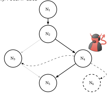
Figure 1: An example for legal and illegal control flows in a CFG. Nodes N1-N5 denote executions of code, while the arrows denote the different edges. A vulnerability in N4 can allow an attacker to illegally redirect control flow to N3 or a new Node N6.
<details>
<summary>Image 1 Details</summary>
### Visual Description
\n
## Diagram: Network Flow with Anomalies
### Overview
The image depicts a directed graph representing a network flow between six nodes (N1 through N6). The connections between nodes are indicated by arrows, with varying line styles (solid and dashed) suggesting different types of relationships or strengths. A cartoonish devil figure is positioned near node N4, and node N6 is enclosed in a dashed circle, indicating potential anomalies or points of interest.
### Components/Axes
The diagram consists of six nodes labeled N1, N2, N3, N4, N5, and N6. The connections between these nodes are represented by directed edges (arrows). There are no explicit axes or scales. The diagram also includes a visual element of a devil character and a dashed circle around N6.
### Detailed Analysis or Content Details
The network flow can be described as follows:
* **N1 -> N2:** A solid arrow indicates a direct flow from node N1 to node N2.
* **N2 -> N4:** A solid arrow indicates a direct flow from node N2 to node N4.
* **N2 -> N5:** A solid arrow indicates a direct flow from node N2 to node N5.
* **N3 -> N2:** A solid arrow indicates a direct flow from node N3 to node N2.
* **N3 -> N4:** A dashed arrow indicates a flow from node N3 to node N4.
* **N4 -> N6:** A dashed arrow indicates a flow from node N4 to node N6.
* **N5 -> N4:** A solid arrow indicates a flow from node N5 to node N4.
The devil figure is positioned to the right of node N4, seemingly observing or influencing the flow. Node N6 is enclosed in a dashed circle, visually separating it from the other nodes. The arrow pointing to N6 is also dashed.
### Key Observations
* Node N4 appears to be a central hub, receiving input from N2, N3, and N5.
* The dashed lines suggest weaker or less direct connections compared to the solid lines.
* The presence of the devil figure near N4 and the dashed circle around N6 suggest these elements are potentially problematic or require further investigation.
* N6 is only reached via a dashed line from N4.
### Interpretation
This diagram likely represents a system or process where data or resources flow between different components (nodes). The solid and dashed lines could represent different levels of trust, security, or reliability in the connections. The devil figure near N4 suggests that this node might be a source of malicious activity or a point of vulnerability. The dashed circle around N6 indicates that this node is potentially compromised, anomalous, or requires special attention.
The diagram could be illustrating a security threat model, a data flow diagram with potential vulnerabilities, or a network topology with identified risks. The use of visual cues like the devil and the dashed circle emphasizes the importance of monitoring and securing nodes N4 and N6. The flow from N3 to N4 is also dashed, suggesting a less reliable or secure connection. The overall structure suggests a system where information flows from initial nodes (N1, N3) through a central hub (N4) to a potentially vulnerable endpoint (N6).
</details>
executed the expected sequence of commands. To ensure the integrity of the verifier even in case of a compromised target or prover, verifier and prover are clearly separated.
To perform the verification, the verifier first collects all legal control flows of the target and calculates its legitimate ControlFlow Graph (CFG). In this CFG, the target's execution is abstractly represented with nodes representing uninterruptible instruction sequences and edges representing transitions between nodes. Figure 1 shows a CFG consisting of the nodes N1 -N5 and five solid edges marking valid transitions between the nodes. In this example, the target first reads input in N1 and compares it to a stored password in N2. Afterwards, the target will either continue to N3 if the input and the password matched or to N4 if the authentication failed. Finally, both N3 and N4 will hand control to N5, which returns the data fetched in N3 or N4.
To create the target's CFG, the verifier can either make use of static or dynamic analysis. With static analysis, the verifier analyzes the binary code of the target to create the CFG. However, this approach cannot include edges calculated at run-time, such as indirect calls. In comparison, dynamic analysis avoids such issues by executing the target to collect all possible paths of the CFG. For this, the verifier executes the target with different inputs and merges all executed paths to the CFG. Yet, using this approach, it is difficult to determine the point at which the target executed all possible control flows at least once. Therefore, efficiently creating complete CFGs for complex programs is still an open research question. To facilitate the invocation of all control flows, one can resort to programs with reduced complexity.
Now,let us assume that N4 contains a vulnerability which enables an attacker to read and write arbitrary data memory. This would allow the attacker to perform a control flow attack and, for example, to modify a return address on the stack. With the modified return
address, the target might then create a new edge by jumping directly from N4 to N3. Overwriting the return address would also allow for the creation of a new node N6 to perform ROP [56].
CFA can detect such attacks. Once the verifier has calculated the CFG, the prover records the execution path of the target and sends it to the verifier. By analyzing the execution path, the verifier can determine if the recorded path was within the expected CFG. If this is not the case, the verifier can conclude that the target has been compromised. The verifier can then trace back the target's execution path to determine the first mismatching edge, allowing to locate the node in which the compromise has first taken effect.
In comparison, Control-Flow Integrity (CFI) verifies edges before their execution by comparing them against meta data of permitted backward [14] or forward edges [13]. To protect this data from attackers, CFI commonly relies on information hiding [70]. Yet, the past has seen various attacks which were nevertheless able to identify and modify the hidden data, thereby circumventing the CFI protection [28, 29, 48]. To defend against such attacks, CFA strictly separates prover and verifier, allowing required meta data to be safely stored on the verifier.
## 3 THREAT MODEL
In this work, we focus on cloud environments, providing us with a virtual machine with full administrative privileges, as it is a common case in such environments. This virtual machine runs the service which we aim to protect, our target. As with most services, we have to assume that the target's clients are potentially malicious. By exploiting vulnerabilities in the target, a malicious client can gain full control over the target's memory at a specific point in time. While we do assume that the target is protected by techniques such as Data Execution Prevention, the attacker will still have full control over the target's data memory. Being in control over the data memory, the attacker can perform control flow attacks (Section 2.2).
As we are hosting the target in a cloud environment, we further consider the possibility of a malicious administrator controlling the software and hardware infrastructure. Whether this attacker gained access to the infrastructure by escaping a virtual machine [16, 17, 58, 63] hosted on the same physical system, or the infrastructure has been set up for malicious purposes is of no importance. Having control over the infrastructure, the malicious administrator can extract and modify data and processes within our virtual machine. The attacker can either achieve this goal by using software-based methods, such as Virtual Machine Introspection [27], or hardware-based methods, such as DMA [7, 9] or cold boot attacks [30]. However, we do not consider advanced physical attacks such as tapping buses or dismantling the CPU. In other words, we assume the same threat model for a malicious administrator as TEEs such as Intel SGX [19].
## 4 DESIGN
The main goal of GuaranTEE is to detect control flow attacks in untrusted cloud environments, posing several challenges to overcome. In this section, we identify those challenges and present our respective solutions that form the design of GuaranTEE. After giving an overview of our design, we continue with explaining the details of its two phases, the offline and the online phase.
## 4.1 Overview
In cloud environments, the target to be attested will likely be a service, such as a signing service for health certificates. These services are deployed within the European Union to sign the so-called Digital Green Certificates providing proof of vaccination against or recovery from COVID-19 or a negative test result [23]. To avoid the forging of health certificates, it is important that the service's private key is equally protected from a malicious administrator and client. GuaranTEE protects the target signing service against both types of adversaries: By using a TEE, GuaranTEE prevents an administrator from accessing the service's private key. Additionally, it allows to detect a client compromising the service. In the event of such a compromise, the service owner can use the collected information to identify and resolve the vulnerability. Then, by installing a new private key and revoking health certificates signed with the old key, the impact of the attack can be minimized.
Another relevant aspect of signing services is that they only sign newly created health certificates and are therefore only required to provide a limited throughput. In other words, their performance is of much lower priority than their security guarantees, which could be threatened by a malicious client. To protect against such a threat, we move the attestation away from the client to another, trusted entity. To be precise, contrary to previous designs for CFA [1, 22, 61, 68], in which the client attests a remote execution, we assign this task to the owner of the service. This separation serves three purposes. First, it allows us to leave the interface between the client and the service unchanged, making GuaranTEE transparent to the client. Second, it enables us to perform CFA without requiring any information from the client, for example to ensure the freshness of the attestation [1, 2, 18, 22, 60, 61, 68]. Third, it allows us to perform the attestation time-independent from the communication between client and service.
Another concern in cloud environments is that we cannot rely on the underlying infrastructure, as it might be controlled by a malicious administrator. To protect against this threat, we use TEEs. Specifically, we place both target and verifier in a separate TEE, shielding them from attacks by a malicious administrator. By using two different TEEs, we additionally limit the influence of a malicious client on the verifier after exploiting vulnerabilities in the target.
When choosing a TEE, we have to consider that cloud environments are limited in the choice of available hardware. Further, we are not able to perform any hardware modifications, requiring us to use the TEE offered by the cloud provider. Therefore, we discuss GuaranTEE's design based on the generic concepts of TEEs, preserving the flexibility of which TEE to choose. In Section 5, we show how GuaranTEE can be used in the example of Intel SGX.
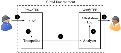
Figure 2 depicts the generic design of GuaranTEE. The dashed line indicates the cloud environment offered by the cloud provider. Within this environment, we create two TEEs, the ProveTEE and the VerifyTEE . The ProveTEE is responsible for hosting the target. Further, it also contains the trampoline , responsible for collecting the control flow executed by the target. We insert the trampoline at compile-time, making it transparent to the client. In comparison, the VerifyTEE hosts the analyzer , responsible for verifying the control flow collected by the trampoline. After verification, the analyzer stores the result in the attestation log also located in the
Figure 2: The generic design of GuaranTEE. By using TEEs, we prevent a malicious administrator from extracting or modifying critical data. Additionally, the separation into two TEEs ensures that a malicious client is not able to influence CFA results by compromising the target or the ProveTEE.
<details>
<summary>Image 2 Details</summary>
### Visual Description
\n
## Diagram: Cloud Environment Attestation Flow
### Overview
The image depicts a diagram illustrating a cloud environment attestation flow between a user, a "ProveTEE" component, and a "VerifyTEE" component. The diagram shows the sequence of interactions and data flow for verifying the integrity of a target environment. The entire process is contained within a box labeled "Cloud Environment".
### Components/Axes
The diagram consists of the following components:
* **User (Left):** Represented by a cartoon figure wearing a hoodie.
* **ProveTEE:** A rectangular block containing "Target" and "Trampoline" components.
* **VerifyTEE:** A rectangular block containing "Analyzer" and "Attestation Log" components.
* **Target:** A component within ProveTEE.
* **Trampoline:** A component within ProveTEE.
* **Analyzer:** A component within VerifyTEE.
* **Attestation Log:** A component within VerifyTEE.
* **Cloud Environment:** A dashed-line rectangle encompassing ProveTEE and VerifyTEE.
* **Numbered Arrows:** Indicate the flow of data/interaction. Numbers 1 through 5 mark the sequence.
### Detailed Analysis / Content Details
The diagram illustrates the following sequence of events:
1. **User to ProveTEE:** An arrow (labeled '1') originates from the user and points towards the "Target" component within "ProveTEE". This represents an initial request or interaction.
2. **Target to Trampoline:** An arrow (labeled '2') originates from the "Target" component and points to the "Trampoline" component within "ProveTEE". This suggests a transition or execution flow within the trusted environment.
3. **Trampoline to Analyzer:** An arrow (labeled '3') originates from the "Trampoline" component and points to the "Analyzer" component within "VerifyTEE". This indicates the transfer of data or attestation information.
4. **Analyzer to Attestation Log:** An arrow (labeled '4') originates from the "Analyzer" component and points to the "Attestation Log" component within "VerifyTEE". This suggests the recording of analysis results.
5. **Attestation Log to User:** An arrow (labeled '5') originates from the "Attestation Log" component and points to the user. This represents the final attestation result being delivered to the user.
### Key Observations
The diagram highlights a clear separation between the "ProveTEE" and "VerifyTEE" components. The flow is sequential, starting with a user request, proceeding through the trusted execution environment ("ProveTEE"), analysis by "VerifyTEE", and finally, a result delivered back to the user. The "Trampoline" component within "ProveTEE" suggests a mechanism for transitioning between different execution contexts or security domains.
### Interpretation
This diagram illustrates a remote attestation process within a cloud environment. The "ProveTEE" component likely represents a Trusted Execution Environment (TEE) where sensitive computations are performed. The "Target" could be the application or code being attested. The "Trampoline" might be a mechanism to enter or exit the TEE. The "VerifyTEE" component acts as a verifier, analyzing the attestation data provided by the TEE and recording the results in the "Attestation Log". The user receives the final attestation result, confirming the integrity of the target environment.
The diagram suggests a security model where a remote party (the user) relies on a trusted third party ("VerifyTEE") to verify the integrity of a remote computation ("ProveTEE"). This is a common pattern in cloud security, where users need to trust that their data and computations are being performed in a secure and trustworthy environment. The numbered arrows are crucial for understanding the order of operations and the flow of information.
</details>
VerifyTEE. The VerifyTEE itself is entirely passive: its tasks are the analysis of control flow data received from the trampoline and the provision of the attestation log to the service owner. Furthermore, the VerifyTEE may be equipped with additional functionalities such as deploying target-specific mitigations or shutting down the target and its service, which are out of the scope of this paper.
Before the VerifyTEE is able to detect control flow attacks, we require an offline phase in which the analyzer learns the target's CFG (Section 4.2). Afterwards, in the online phase, the client sends regular requests to the target ( ❶ ). While the target is processing the request, the trampoline records the control flow ( ❷ ). Next, the trampoline forwards the information to the analyzer in the VerifyTEE ( ❸ ). The forwarding prevents an attacker in control of the target or even the entire ProveTEE from tampering with the control-flow analysis. Having received the information from the trampoline, the analyzer compares the collected control flow against the target's CFG. Next, it stores the result of this comparison in the attestation log ( ❹ ). Finally, the service owner is able to retrieve the attestation log from the VerifyTEE ( ❺ ) to perform the deferred attestation of the target's control flows.
## 4.2 Offline Phase
In the offline phase, we prepare the environment. For this preparation, we instrument the target to regularly pass control to the trampoline. This instrumentation enables the trampoline to record the target's executed edges ( ❷ ) and to provide this information to the analyzer ( ❸ ). As we perform the instrumentation at compile-time, we do not require any high-level modifications. Instead, the developer only needs to annotate where the attestation of the target's control flow should start and end. This makes our instrumentation transparent to the target's clients, as the interface between the client and the target remains unchanged.
Once the trampoline is able to record the target's control flow, we calculate the target's CFG by sending requests to the target until it has executed every control flow path at least once. To ensure that no malicious paths are followed, we perform this step in a safe environment without any possibly malicious clients. During the dynamic execution, the analyzer collects all recorded control flows and merges them into the CFG.
Yet, determining the point at which a complex target has executed all legal control flows is still an open research question. Therefore, GuaranTEE aims to protect targets with reduced complexity that are frequently deployed in cloud environments, the so-called microservices. Such microservices split the functionality of a complex multi-functional service into multiple, simple services with a single functionality. This reduced functionality also reduces the complexity of each service, simplifying the execution of all legal control flows for each of them. As an alternative to splitting up the target itself, we can break down the CFG of a complex target into multiple segments to facilitate the collection of each segment's CFG, as suggested by previous work [2, 61].
Another difficulty for the creation of the CFG is that in cloud environments we likely have to deal with Address Space Layout Randomization (ASLR) [57]. ASLR causes the target to use different virtual addresses at every launch, preventing us from using addresses to identify the endpoints of edges in the CFG. Instead, we identify the endpoints by assigning them unique IDs , leaving the identification unaffected by ever-changing virtual addresses.
Having determined the target's full CFG, the analyzer is able to detect control flow attacks on the target. Additionally, having access to the full CFG enables the analyzer to identify the node in which the compromise has first shown effect.
## 4.3 Online Phase
During the online phase, the target hosted in the ProveTEE waits for requests from potentially malicious clients ( ❶ ). As GuaranTEE is transparent to the clients, they can send the same requests to the instrumented target as to the original.
While the target processes the request, it records all IDs and provides them to the trampoline ( ❷ ). Yet, the trampoline itself is not responsible for processing the IDs. This is due to the fact that it runs in the ProveTEE, next to the target. Hence, an attacker gaining control over the target could also tamper with the trampoline. To ensure that such an attack does not influence the CFA, we outsource the analysis task to the VerifyTEE. Specifically, the only task of the trampoline is to forward the collected IDs to the analyzer in the VerifyTEE ( ❸ ). This approach has two advantages. First, it reduces the trampoline's processing time. And second, it protects the analysis from an attacker in control of the target and the ProveTEE.
Next, the analyzer uses the received IDs to reconstruct the target's control flow. By then comparing the control flow against the target's CFG created in the offline phase (Section 4.2), the analyzer can detect control flow attacks. After the control-flow attestation, the analyzer stores the respective result in the attestation log ( ❹ ).
Finally, the service owner fetches the attestation log from the VerifyTEE ( ❺ ). This log contains all requests which altered the target's control flow, allowing for a deferred attestation of the target. When such requests have been logged, the service owner can take appropriate actions. In the example of our signing service, this would include the revocation of erroneously signed certificates as well as analyzing and resolving bugs in the target's code.
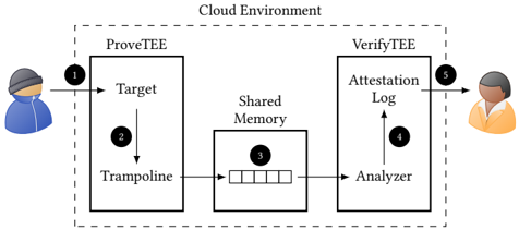
Figure 3: Overview of our prototype based on the GuaranTEE design. The additional shared memory region allows to transfer the IDs collected by the trampoline to the analyzer in the VerifyTEE.
<details>
<summary>Image 3 Details</summary>
### Visual Description
\n
## Diagram: Cloud Environment Attestation Flow
### Overview
The image depicts a diagram illustrating a cloud environment attestation flow between a user and a cloud service. The flow involves two main components: ProveTEE and VerifyTEE, connected via shared memory. The diagram uses numbered arrows to indicate the sequence of operations.
### Components/Axes
The diagram consists of the following components:
* **Cloud Environment:** A dashed rectangle encompassing the entire process.
* **ProveTEE:** A rectangular block representing the trusted execution environment where the target application resides. Contains "Target" and "Trampoline" components.
* **VerifyTEE:** A rectangular block representing the trusted execution environment responsible for verifying the attestation. Contains "Attestation Log" and "Analyzer" components.
* **Shared Memory:** A rectangular block representing the shared memory space between ProveTEE and VerifyTEE. Contains a data structure represented as a series of rectangles.
* **User (Left):** A cartoon figure representing the user initiating the process.
* **Verifier (Right):** A cartoon figure representing the entity verifying the attestation.
* **Arrows (1-5):** Numbered arrows indicating the flow of data and control.
### Detailed Analysis or Content Details
The diagram illustrates the following flow:
1. **User to Target:** An arrow labeled "1" points from the user (left) to the "Target" component within ProveTEE. This represents the initial request or invocation of the target application.
2. **Target to Trampoline:** An arrow labeled "2" points from the "Target" component to the "Trampoline" component within ProveTEE. This indicates a transition or handover of control.
3. **Trampoline to Shared Memory:** An arrow labeled "3" points from the "Trampoline" component to the "Shared Memory". This represents writing attestation data into the shared memory. The data in shared memory is represented as a series of rectangles.
4. **Shared Memory to Analyzer:** An arrow labeled "4" points from the "Shared Memory" to the "Analyzer" component within VerifyTEE. This indicates the Analyzer reading the attestation data from shared memory.
5. **Analyzer to Verifier:** An arrow labeled "5" points from the "Analyzer" component to the verifier (right). This represents the final attestation result being delivered to the verifier.
### Key Observations
The diagram highlights a secure attestation process where the ProveTEE generates evidence of its state and writes it to shared memory. The VerifyTEE then reads this evidence and provides it to the verifier. The use of shared memory facilitates communication between the two trusted execution environments. The numbered arrows clearly define the sequence of operations.
### Interpretation
This diagram illustrates a typical architecture for remote attestation in a cloud environment. The ProveTEE component is responsible for generating a cryptographic attestation of the target application's state. This attestation is then securely transferred to the VerifyTEE component via shared memory. The VerifyTEE component analyzes the attestation and provides a verification result to the verifier. This process ensures that the verifier can trust the integrity of the target application running in the cloud environment. The use of a trampoline suggests a mechanism for transitioning between different security domains or privilege levels. The shared memory acts as a secure channel for exchanging sensitive attestation data. The diagram does not provide specific details about the attestation protocol or the cryptographic techniques used, but it provides a high-level overview of the attestation flow.
</details>
## 5 IMPLEMENTATION
Based on our design, we implemented the GuaranTEE prototype using Intel SGX (Section 2.1) as TEE. The reason for this choice is that SGX is supported by most modern Intel CPUs and is also widely available in cloud environments [25, 34, 37, 53]. In this section, we discuss implementation details of the prototype, such as the instrumentation of the target and the distribution of work between different threads.
## 5.1 Overview
Figure 3 gives an overview of our implementation. The basic building blocks are the same as in the design (Section 4), except the additional shared memory region used to exchange data between the ProveTEE and the VerifyTEE. This region allows the TEEs to exchange information without requiring any context switches, thereby reducing the performance overhead of the communication.
To create the shared memory region, we make use of the fact that SGX TEEs share the virtual address space with their Host Application (HA) [55]. Specifically, by using the same HA to launch both the ProveTEE and the VerifyTEE, both TEEs will share the same virtual address space [44]. This enables us to allocate a memory region in the HA which both the ProveTEE and the VerifyTEE can access, allowing them to exchange collected IDs. Note that while both TEEs are able to read and write the shared memory, they are not able to access each other's memory.
The first step of our GuaranTEE prototype is to perform an offline phase, in which it collects all of the target's control flows to calculate its CFG (Section 4.2). Afterwards, our prototype verifies the target's control flow in the online phase and provides the verification results to the service owner (Section 4.3).
In the implementation, each basic block in the target corresponds to a node in the CFG. The basic blocks are connected via edges, the endpoints of which are recorded by the trampoline. To be precise, the target calls the trampoline each time before entering or exiting a basic block, providing the ID of the respective endpoint. The trampoline stores this ID in an ID batch , which acts as a cache.
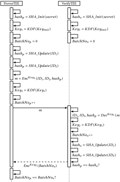
Figure 4 depicts how we are able to securely cache the IDs by combining them with the calculation of a new key for every data exchange and tracking the number of exchanged ID batches. To
)
Figure 4: The exchange of IDs between the ProveTEE and the VerifyTEE. To ensure the integrity of IDs cached in the ID batches, we make use of a hash chain. Additionally, we calculate a new encryption key for every exchange with the help of a KDF and record the number of the current batch.
<details>
<summary>Image 4 Details</summary>
### Visual Description
\n
## Diagram: Secure Multi-Party Computation Protocol Flow
### Overview
The image depicts a sequence diagram illustrating a secure multi-party computation protocol between two entities: a "ProverTEE" and a "VerifyTEE". The diagram shows the flow of messages and operations performed by each entity to verify a batch of data. The diagram uses boxes to represent operations and arrows to represent message passing.
### Components/Axes
The diagram consists of two vertical columns representing the "ProverTEE" (left) and "VerifyTEE" (right). Each column contains a series of rectangular boxes representing operations, connected by arrows indicating the flow of data or control. The diagram also includes dashed arrows to indicate conditional operations.
### Detailed Analysis or Content Details
**ProverTEE (Left Column):**
1. `hashp = SHA_Init(secret)`
2. `Key1 = KDF(Keyinit)`
3. `BatchNop = 0`
4. `hashp = SHA_Update(ID1)`
5. `hashp = SHA_Update(ID2)`
6. `m = EncKey1(ID1, ID2, hashp)`
7. `Key2 = KDF(Key1)`
8. `BatchNop++`
9. Message `m` is sent to VerifyTEE.
10. `EncKey2(BatchNop)` is sent to VerifyTEE (dashed arrow, conditional).
11. `BatchNop == BatchNo?` (conditional, end of flow)
**VerifyTEE (Right Column):**
1. `hasho = SHA_Init(secret)`
2. `Key1 = KDF(Keyinit)`
3. `BatchNoo = 0`
4. `hasho = SHA_Update(ID1)`
5. `hasho = SHA_Update(ID2)`
6. Message `m` is received from ProverTEE.
7. `ID1, ID2, hashp = DecKey1(m)`
8. `Key2 = KDF(Key1)`
9. `BatchNoo++`
10. `hasho = SHA_Update(ID1)`
11. `hasho = SHA_Update(ID2)`
12. `hashp == hasho?` (conditional)
**Variables and Functions:**
* `hashp`, `hasho`: Hash values.
* `Key1`, `Key2`: Keys derived using a Key Derivation Function (KDF).
* `BatchNop`, `BatchNoo`: Batch numbers.
* `ID1`, `ID2`: Identifiers.
* `m`: Encrypted message.
* `SHA_Init(secret)`: Initializes a SHA hash with a secret.
* `KDF(Keyinit)`: Key Derivation Function.
* `SHA_Update(ID)`: Updates the SHA hash with an identifier.
* `EncKey1(ID1, ID2, hashp)`: Encrypts data using Key1.
* `DecKey1(m)`: Decrypts data using Key1.
* `EncKey2(BatchNop)`: Encrypts the batch number using Key2.
### Key Observations
The diagram illustrates a protocol where the ProverTEE proves the correctness of a batch of data (represented by `ID1` and `ID2`) to the VerifyTEE. The protocol uses encryption, hashing, and key derivation to ensure security and integrity. The conditional checks (`BatchNop == BatchNo?` and `hashp == hasho?`) are crucial for verifying the batch and the hash values. The use of `SHA_Update` suggests that the hash is being incrementally built.
### Interpretation
This diagram represents a secure computation protocol likely used in a Trusted Execution Environment (TEE) setting, as indicated by the "TEE" suffix in the entity names. The protocol aims to verify data integrity and authenticity. The ProverTEE generates a proof (`m`) based on the data and a secret, and the VerifyTEE verifies this proof. The use of KDFs ensures that keys are derived securely from initial secrets. The batch numbers (`BatchNop` and `BatchNoo`) suggest that the protocol can handle multiple data items in a batch. The conditional checks at the end ensure that the batch number and hash values match, confirming the validity of the proof. The dashed arrow indicates a conditional message exchange, likely triggered by a successful verification. The protocol appears to be designed to prevent the VerifyTEE from learning the secret used by the ProverTEE, while still allowing it to verify the data's integrity. The use of SHA hashing provides collision resistance and ensures data integrity. The overall design suggests a commitment-and-verification scheme.
</details>
ensure the integrity of the cached IDs in the ProveTEE, we make use of a hash chain. The root of this hash chain is a secret we provide to both the ProveTEE and the VerifyTEE. When we cache an ID in the ID batch, we update the hash in the ProveTEE, ℎ𝑎𝑠ℎ 𝑝 , with the new ID. If the ID batch is full, we combine it with the current value of ℎ𝑎𝑠ℎ 𝑝 to form a single message, which we then encrypt and store in the queue located in the shared memory region. After the VerifyTEE reads and decrypts the message from the queue, it adds all IDs to its own hash, ℎ𝑎𝑠ℎ 𝑣 . As we initialize both ℎ𝑎𝑠ℎ 𝑝 and ℎ𝑎𝑠ℎ 𝑣 with the same secret and add the same IDs to both hashes, ℎ𝑎𝑠ℎ 𝑣 should equal the value of ℎ𝑎𝑠ℎ 𝑝 transmitted with the batch. To minimize the performance impact of this step, our prototype uses BLAKE3 as hash algorithm [49].
When exchanging the ID batch via shared memory, we have to keep in mind that the memory is also accessible to other, untrusted
entities such as the HA or the operating system. This means that a malicious administrator would be able to inspect and modify transferred ID batches. To protect the batches from such attacks, we implement mechanisms which ensure their confidentiality and integrity. For confidentiality, we provide both TEEs with an initial encryption key, 𝐾𝑒𝑦 𝐼𝑛𝑖𝑡 . Both TEEs use this initial key as input to a Key Derivation Function (KDF) to calculate an encryption key. For the following messages, the encryption key serves as input for the KDF to produce a new key for the next message, allowing us to calculate a new key for each message. These keys enable us to encrypt the ID batches and the respective hash values before writing them into shared memory, ensuring that they cannot be inspected by a malicious administrator. By additionally calculating a new key for every message, we ensure that an attacker in control of the ProveTEE cannot infer previously used keys. We achieve this by calculating the keys with an irreversible KDF and by deleting old keys after usage. To be precise, we again make use of BLAKE3, as it is irreversible and already integrated in our prototype.
To ensure the integrity of the communication, we use AESGCM for encryption, which additionally provides integrity protection [42]. AES-GCM requires an IV, which we need to synchronize between the trampoline and the analyzer to ensure correct encryption and decryption. We achieve this synchronization by managing an independent counter, BatchNo , in both the ProveTEE and the VerifyTEE. After each encryption or decryption, we increase the counter to keep both counters synchronized. These counters allow us to detect attacks in which the malicious administrator prevents forwarding of the ID batches. For this detection, the VerifyTEE regularly acknowledges the receipt of the ID batches. On the other side, the ProveTEE, having stored a certain number of ID batches into the queue, will wait for an acknowledgment before continuing to execute the target. We define the frequency of these acknowledgments as the feedback frequency . In Section 6, we analyze the performance and security impact of different feedback frequencies.
## 5.2 Instrumentation
For the automatic instrumentation of the target, we rely on the LLVM compiler framework. The instrumentation allows us to establish the target's CFG in the offline phase (Section 4.2) and to verify its control flows in the online phase (Section 4.3).
To calculate the CFG, we need to determine all edges executed by the target. Each edge has two endpoints: the exit from a basic block and the entry into another basic block, both of which we identify with a unique ID. By analyzing the recorded IDs, we can reconstruct all edges executed by the target and therefore its full control flow. To collect the IDs, we add calls to the trampoline on every entry and exit of each basic block.
To instrument all entries and exits, we modify two different phases of the LLVM compilation process: the IR optimization and the backend. In our IR pass, we add calls to the trampoline at the beginning and the end of each basic block and before and after direct function calls. To assign a unique ID for each endpoint, we make use of a counter.
In our backend pass, we instrument all indirect branches. Specifically, we add calls to the trampoline before and after every indirect function call, before every indirect jump, and before every return instruction. As before, each trampoline call is associated with a unique ID, allowing us to identify the endpoints of all executed edges in the target's control flow. Additionally, on indirect calls, indirect jumps, and returns we XOR the ID with the offset between the current instruction pointer and the jump destination to detect modifications of the jump address. This safeguard allows us to detect jumps from instrumented into uninstrumented code. Specifically, it causes a modification of the jump destination to also change the recorded ID, allowing us to detect the modification even if it points the execution to uninstrumented code. Being able to record all control flows, we use the offline phase to combine the collected IDs to the target's CFG.
While it may technically be possible to perform all instrumentations in IR only, the backend pass allows us to precisely place the calls to the trampoline. For example, let us consider ROP attacks in which gadgets consist of the last instructions before a return instruction [56]. To detect such attacks, we need to place the call to the trampoline as close to the return instruction as possible. When adding the call in IR, the subsequent code generation in the backend will insert instructions for stack cleanup between the call and the return instruction. This would allow execution of these instructions without invoking the trampoline, providing a potential ROP gadget. In comparison, using our backend pass, inserting the call during code generation allows us to place the call as close to the return instruction, or any other indirect branch instruction, as possible. Note that we do not consider the instructions before direct function calls as possible ROP gadgets due to the hard-coded function address. Hence, we refrain from instrumenting direct function calls in the backend pass and instead instrument them in our IR pass.
## 5.3 Execution
The instrumentation of the target allows us to use dynamic execution to record the IDs in the offline phase (Section 4.2). For this, we created a script which performs a variety of requests, causing the target to execute each valid control flow at least once. During processing of these requests, the analyzer investigates the IDs and creates the target's CFG. We then switch to the online phase, in which the analyzer uses the CFG to detect control flow attacks.
In the online phase, the GuaranTEE prototype performs CFA for all control flows between a start and end point annotated by the developer. Using for example our signing service, we annotated the initialization and the termination of an incoming connection. The annotations cause the trampoline to send a special begin or end tag to the analyzer, triggering it to start or stop the analysis. This additional analysis task unavoidably slows down the processing time of a request. To minimize this impact, we make use of the high processing power of cloud systems. Specifically, we provision our virtual machine with multiple vCPUs, thus supporting parallel processing of different tasks. To fully capitalize on this ability, we distribute the prototype's tasks between two threads: the prover thread and the verifier thread .
The prover thread is responsible for executing the target to process incoming requests. Additionally, it executes the trampoline to collect the IDs in batches and to store them in the shared queue. In detail, within the prover thread, the target waits for and processes incoming requests ( ❶ ). During processing, the thread jumps to
the trampoline on every instrumentation ( ❷ ), which caches the recorded ID in the ID batch and extends the hash chain. When an ID batch is full, the trampoline encrypts it with AES-GCM, using the key derived with the KDF (Section 5.1). Afterwards, it stores the encrypted ID batch in the queue ( ❸ ). When the trampoline finished its execution, the prover thread returns to the target to continue processing the request.
In comparison, the verifier thread is responsible for the reconstruction of the target's control flow. It reads the IDs provided by the prover thread, validates them against the CFG learned in the offline phase, and stores the validation result in the attestation log. To fulfill these tasks, the verifier thread reads the encrypted ID batches from the queue and decrypts them with the key derived from the KDF (Section 4.1). Next, it forwards the IDs contained in the ID batches to the analyzer. Using the IDs, the analyzer rebuilds the target's control flow and verifies it against the target's CFG. After the analyzer finished this verification, the verifier thread stores the respective result in the attestation log ( ❹ ). Afterwards, it checks if new ID batches exist in the queue to continue the attestation.
The most efficient method to synchronize our two threads would be a mutex [46]. Unfortunately, SGX does not yet support the use of mutexes to synchronize multiple threads running in different enclaves. Instead, our prototype currently has to rely on atomic operations [26] to add or read ID batches to or from the queue. Additionally, we use a spinlock [64] while the verifier thread waits for the prover thread to add new ID batches to an empty queue.
To retrieve the verification results ( ❺ ), GuaranTEE allows the service owner to access the attestation log in a protected manner. For this access, the service owner confirms the integrity of the VerifyTEE using remote attestation [4, 35, 54]. This attestation process establishes a TLS connection, thereby creating an encrypted channel directly into the TEE [38]. Using this encrypted channel, the service owner is able to securely retrieve the attestation log.
To summarize, the analyzer uses the offline phase to calculate the target's CFG. In the online phase, it verifies the target's recorded control flow by comparing the IDs with the previously constructed CFG. To reduce the impact of this analysis on the target's processing time, we split the tasks between two threads, the prover thread and the verifier thread. While the prover thread executes the target and collects its control flow information, the verifier thread analyses the collected information.
## 6 EVALUATION
To precisely evaluate the overhead of the different steps of our design, we analyzed the processing times of the different components ( ❷ -❹ ) individually. Additionally, we evaluated the performance overhead and the security of the entire prototype.
## 6.1 Setup
As target for the evaluation, we created a microservice responsible for signing health certificates (Section 4.1). Our signing service receives the hash of a newly created health certificate, signs the hash with its private key, and returns the signature. The service performs this exchange via a secure connection, which we establish based on code from the SGX-OpenSSL project [31]. This code allows clients to establish a TLS channel directly into the TEE. By using annotations, we instructed GuaranTEE to perform the CFA between receiving and terminating an incoming connection. In total, our signature service consists of 4 , 533 instructions, excluding libraries such as OpenSSL, and the trampoline of 47 , 542 instructions.
As traditional time measurements are not available within SGX TEEs [11], we added an ocall to both TEEs which notifies the HA to start or stop a measurement. By executing this ocall at the start and at the end of our measurements, we were able to determine the difference between those two points in time in the HA.
We performed our measurements in the Microsoft Azure cloud environment on a Standard DC4s\_v2 machine with an Intel Xeon E2288G CPU, four vCPUs, and 16 GiB of memory. Within the virtual machine, we were running the default Ubuntu 18 . 04 provided by Azure and the Linux SGX DCAP driver in version 𝑣 1 . 41.
## 6.2 Benchmark Performance Evaluation
To determine the throughput of GuaranTEE in extreme conditions, we deployed a benchmark as the target before evaluating the performance of our signing service. We used the sgx-nbench benchmark suite [62], which is a port of nbench [50] to SGX. As a baseline, we ran the benchmark without instrumentation. Then, we instrumented the target with GuaranTEE and used our default configuration of an ID batch size of 10 , 000 and a feedback frequency of 10. In Sections 6.3 and 6.4, we analyze the impact of different batch sizes and feedback frequencies.
Table 1: Comparison of sgx-nbench with and without GuaranTEE. Measurements are in iterations per second.
| Test | Baseline | GuaranTEE | Overhead |
|--------------|-----------------|-----------------|------------|
| Numeric Sort | 2 , 387 . 2 | 11 . 4 | 208x |
| String Sort | 1 , 285 . 1 | 42 . 2 | 29x |
| Bitfield | 9 . 3382 ∗ 10 8 | 3 . 0783 ∗ 10 6 | 302x |
| FP Emulation | 1 , 251 | 12 | 103x |
| Fourier | 62 , 574 | 11 , 438 | 4x |
| Assignment | 121 . 51 | 0 . 17 | 713x |
| Idea | 21 , 500 | 55 | 390x |
| Huffman | 6 , 509 . 4 | 49 . 3 | 131x |
| Neural Net | 192 . 77 | 1 . 00 | 192x |
| LU Decomp. | 4302 . 4 | 23 . 5 | 182x |
| Average | - | - | 225x |
Table 1 shows the overhead of GuaranTEE for the sgx-nbench benchmark suite. The overhead varies between 4x for the Fourier Test and 713x for the Assignment Test. On average, we recorded an overhead of 225x between the baseline and the instrumented benchmarks. Having determined this relatively high overhead, it is important to note that in comparison to most targets, a benchmark evaluates the performance under extreme conditions, such as a very high CPU load. In contrast, a regular target, such as our signing service, will also perform less resource-intensive operations such as waiting for the operating system or for incoming network traffic. This will reduce the overhead of a regular target in comparison to the evaluated benchmark. To prove this claim, we continue by evaluating GuaranTEE's different components using our signing service as the target.
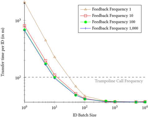
Figure 5: Average time required to transfer a single ID from the trampoline to the analyzer ( ❸ ). While the impact of the feedback frequency is limited, the transfer time drastically decreases with higher batch sizes.
<details>
<summary>Image 5 Details</summary>
### Visual Description
## Chart: Transfer Time vs. ID Batch Size for Different Feedback Frequencies
### Overview
The image presents a line chart illustrating the relationship between ID Batch Size and Transfer Time per ID (in nanoseconds) for four different Feedback Frequencies. The chart demonstrates how transfer time decreases as the ID Batch Size increases, with varying degrees of reduction depending on the feedback frequency. A horizontal dashed line represents the "Trampoline Call Frequency".
### Components/Axes
* **X-axis:** "ID Batch Size" - Logarithmic scale, ranging from approximately 10<sup>0</sup> to 10<sup>4</sup>. Markers are at 1, 10, 100, 1000, 10000.
* **Y-axis:** "Transfer time per ID (in ns)" - Logarithmic scale, ranging from approximately 10<sup>0</sup> to 10<sup>3</sup>. Markers are at 1, 10, 100, 1000.
* **Legend:** Located in the top-right corner.
* Feedback Frequency 1 (Orange, Triangle Markers)
* Feedback Frequency 10 (Red, Square Markers)
* Feedback Frequency 100 (Green, Diamond Markers)
* Feedback Frequency 1,000 (Blue, Circle Markers)
* **Horizontal Line:** Dashed grey line labeled "Trampoline Call Frequency" at approximately y = 10<sup>2</sup>.
### Detailed Analysis
Let's analyze each data series:
* **Feedback Frequency 1 (Orange):** This line starts at approximately y = 10<sup>3</sup> at x = 1, and slopes steeply downward, reaching approximately y = 20 at x = 100, and leveling off around y = 10 at x = 1000 and x = 10000.
* **Feedback Frequency 10 (Red):** This line begins at approximately y = 10<sup>3</sup> at x = 1, and decreases more gradually than the orange line, reaching approximately y = 80 at x = 100, y = 30 at x = 1000, and y = 15 at x = 10000.
* **Feedback Frequency 100 (Green):** This line starts at approximately y = 10<sup>2</sup> at x = 1, and decreases rapidly to approximately y = 20 at x = 10, y = 10 at x = 100, and remains relatively flat around y = 5 at x = 1000 and x = 10000.
* **Feedback Frequency 1,000 (Blue):** This line begins at approximately y = 10<sup>2</sup> at x = 1, and decreases quickly to approximately y = 10 at x = 10, y = 5 at x = 100, and remains nearly flat around y = 2 at x = 1000 and x = 10000.
### Key Observations
* All lines exhibit a decreasing trend, indicating that increasing the ID Batch Size reduces the Transfer Time per ID.
* The Feedback Frequency 1 line shows the most significant reduction in transfer time initially, but its rate of decrease slows down at larger batch sizes.
* The Feedback Frequency 100 and 1,000 lines converge at larger batch sizes, suggesting that at very large batch sizes, the feedback frequency has minimal impact on transfer time.
* The "Trampoline Call Frequency" line appears to be a performance threshold. The lines with higher feedback frequencies (100 and 1000) fall below this line at larger batch sizes, indicating potentially better performance.
### Interpretation
The data suggests that increasing the ID Batch Size is an effective strategy for reducing transfer time per ID. The optimal feedback frequency depends on the batch size. At smaller batch sizes, a lower feedback frequency (e.g., 1) may be sufficient, but as the batch size increases, higher feedback frequencies (e.g., 100 or 1000) become more beneficial, potentially surpassing the "Trampoline Call Frequency" threshold and achieving better performance. The convergence of the lines at larger batch sizes indicates a point of diminishing returns, where increasing the feedback frequency further does not significantly improve transfer time. This could be due to other bottlenecks in the system. The logarithmic scales on both axes suggest that the relationship between batch size and transfer time is not linear, and that the benefits of increasing batch size are most pronounced at smaller batch sizes. The "Trampoline Call Frequency" likely represents a system overhead or a limit imposed by the underlying architecture.
</details>
## 6.3 Component Performance Evaluation
Using our signing service (Section 6.1), we continued by evaluating the different components of GuaranTEE, namely the instrumented target ( ❷ ), the queue ( ❸ ), and the analyzer ( ❹ ). To evaluate the throughput of the instrumented target ( ❷ ), we simulated 100 , 000 client requests. While processing the requests, the target produced 9 . 87 IDs per microsecond, or, in other words, called the trampoline on average every 101 . 29 ns. We call this frequency, with which the target calls the trampoline, the trampoline call frequency .
Next, we determined the throughput of the queue used to transfer IDs from the trampoline to the analyzer ( ❸ ). For this transfer, the trampoline caches the received IDs in batches (Section 5.1). When an ID batch is full, the trampoline encrypts and stores it into the queue, where the analyzer is able to read it. Having received and successfully decrypted the ID batch, the analyzer gives feedback to the trampoline. Determined by the feedback frequency (Section 5.1), the analyzer can be configured to give feedback only after a certain amount of ID batches has been processed. Using this approach, the throughput with which we can transfer the IDs from the trampoline to the analyzer depends on two variables: the ID batch size and the feedback frequency.
Figure 5 gives an overview of the throughput with different ID batch sizes and feedback frequencies. While the X-axis depicts the different batch sizes, the Y-axis indicates the average transfer time per ID in nanoseconds. Both axes are in logarithmic scale. The four different plots indicate the impact of different feedback frequencies on the transfer time. A feedback frequency of 1 means that the trampoline waits for feedback from the analyzer after every single ID batch. In comparison, using a frequency of 1 , 000, the trampoline only waits for feedback after having transferred 1 , 000 ID batches.
The four different plots show that the feedback frequency has only limited impact on the throughput. While a frequency of 1 does decrease the throughput, the differences between the frequencies 10, 100, and 1 , 000 are only minor. This difference becomes negligible in combination with an ID batch size of 100 or more. In comparison, the ID batch size has a significantly higher impact on the throughput. Using a size of 1, we needed on average 2 , 098 . 11 ns to transfer a single ID with feedback frequency 1, and 665 . 17 ns with a frequency of 1 , 000. Yet, we are able to drastically reduce the transfer time by increasing the ID batch size. For example, our default configuration of an ID batch size of 10 , 000 and a feedback frequency of 10 reduces the transfer time to 37 . 76 ns.
For a better interpretation of these results, the dashed gray line in Figure 5 indicates the trampoline call frequency, which we previously determined to be 101 . 29 ns. All configurations achieving transfer times below this frequency transfer the IDs to the analyzer faster than the target creates new IDs. With our prototype, we stay above this frequency for ID batch sizes below 10. Yet, a size of 10 combined with a feedback frequency of 100 or 1 , 000 already transfers the IDs faster than the trampoline call frequency. Additionally, the transfer time stayed below the trampoline call frequency with an ID batch size of 50 and a feedback frequency of 10 and 1.
Having evaluated the throughput of the target and the queue, we continued by evaluating the analyzer's throughput ( ❹ ). As we consider the offline phase less time-critical, we focused on the evaluation of the online phase. In the online phase, the analyzer verifies the target's control flow by comparing the IDs with the previously recorded CFG. Specifically, it verifies all IDs received between the start and end tag (Section 5.3). With our signing service, the target sends the start tag when the worker thread receives an incoming connection, and the end tag when terminating the connection. This allows us to only attest handling of a request and to exclude other tasks such as waiting for a new connection.
To determine the throughput of the analyzer, we measured the time required to process the IDs of 100 , 000 requests. For each request, the analyzer processed around 539 IDs, for which it required on average 7 . 34 ns per ID. This is significantly lower than the target's trampoline call frequency of 101 . 29 ns. In other words, the analyzer processes incoming IDs faster than they are produced by the target.
## 6.4 Signing Service Performance Evaluation
Having evaluated the throughput of GuaranTEE's components, we continued with evaluating its overall overhead on our signing service. To quantify this overhead, we prepared a TEE running the uninstrumented service and measured the time required to process an incoming request. Using this setup, we performed 100 , 000 valid signing requests, which required on average 54 . 79 𝜇 s per request.
After measuring the processing time of the uninstrumented signing service, we evaluated the processing time when instrumenting the service with GuaranTEE. Specifically, we measured the time required by the prover thread to process the request, cache the IDs produced by the trampoline, and to store the encrypted ID batches in the queue. Additionally, we determined the time taken by the verifier thread to read the encrypted ID batches from the queue, decrypt them, analyze the respective IDs, and store the result in the attestation log. Note that although the verifier thread also spends time actively waiting for new ID batches (Section 5.3), we
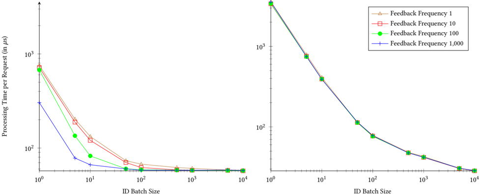
Figure 6: Average processing time for a single request per thread. The left graph depicts the measurements for the prover thread and the right graph for the verifier thread.
<details>
<summary>Image 6 Details</summary>
### Visual Description
\n
## Chart: Processing Time per Request vs. ID Batch Size
### Overview
The image presents a line chart comparing the processing time per request (in microseconds, µs) against the ID batch size. The chart displays four different lines, each representing a different feedback frequency. The x-axis represents the ID Batch Size on a logarithmic scale, while the y-axis represents the Processing Time per Request, also on a logarithmic scale.
### Components/Axes
* **X-axis:** ID Batch Size (Logarithmic scale from 10⁰ to 10⁴)
* **Y-axis:** Processing Time per Request (in µs) (Logarithmic scale from 10⁰ to 10³)
* **Legend:** Located in the top-right corner.
* Feedback Frequency 1 (represented by a triangle marker and a reddish-orange line)
* Feedback Frequency 10 (represented by a square marker and a reddish line)
* Feedback Frequency 100 (represented by a circle marker and a green line)
* Feedback Frequency 1,000 (represented by a plus marker and a blue line)
### Detailed Analysis
The chart consists of four lines, each representing a different feedback frequency.
* **Feedback Frequency 1 (Reddish-Orange):** This line starts at approximately 10³ µs at an ID Batch Size of 10⁰. It rapidly decreases, reaching approximately 10¹ µs at an ID Batch Size of 10¹, then continues to decrease to approximately 10⁰ µs at an ID Batch Size of 10². After that, the line plateaus, remaining relatively constant around 10⁰ µs for ID Batch Sizes ranging from 10² to 10⁴.
* **Feedback Frequency 10 (Reddish):** This line begins at approximately 10³ µs at an ID Batch Size of 10⁰. It decreases more slowly than the Feedback Frequency 1 line, reaching approximately 10² µs at an ID Batch Size of 10¹, and then continues to decrease to approximately 10¹ µs at an ID Batch Size of 10². It then plateaus, remaining relatively constant around 10¹ µs for ID Batch Sizes ranging from 10² to 10⁴.
* **Feedback Frequency 100 (Green):** This line starts at approximately 10³ µs at an ID Batch Size of 10⁰. It decreases rapidly, reaching approximately 10¹ µs at an ID Batch Size of 10¹, and then continues to decrease to approximately 10⁰ µs at an ID Batch Size of 10². It then plateaus, remaining relatively constant around 10⁰ µs for ID Batch Sizes ranging from 10² to 10⁴.
* **Feedback Frequency 1,000 (Blue):** This line begins at approximately 10³ µs at an ID Batch Size of 10⁰. It decreases very rapidly, reaching approximately 10² µs at an ID Batch Size of 10¹, and then continues to decrease to approximately 10¹ µs at an ID Batch Size of 10². It then plateaus, remaining relatively constant around 10¹ µs for ID Batch Sizes ranging from 10² to 10⁴.
All lines exhibit a steep decline in processing time as the ID Batch Size increases from 10⁰ to 10². Beyond an ID Batch Size of 10², the processing time stabilizes for all feedback frequencies.
### Key Observations
* Higher feedback frequencies generally result in lower processing times, especially for smaller ID Batch Sizes.
* The benefit of increasing the feedback frequency diminishes as the ID Batch Size increases.
* For larger ID Batch Sizes (above 10²), the processing time converges for all feedback frequencies.
* The logarithmic scales on both axes emphasize the significant reduction in processing time achieved with increasing ID Batch Size.
### Interpretation
The data suggests that increasing the ID Batch Size significantly reduces processing time per request. This is likely due to the amortization of overhead costs across multiple requests. The feedback frequency also plays a role, with higher frequencies generally leading to lower processing times, particularly when the ID Batch Size is small. However, the impact of feedback frequency diminishes as the ID Batch Size increases, indicating that the benefits of frequent feedback are less pronounced when processing larger batches of IDs.
The convergence of processing times for all feedback frequencies at larger ID Batch Sizes suggests that there is a point of diminishing returns for increasing the feedback frequency. Beyond this point, the overhead associated with providing feedback outweighs the benefits. This information is valuable for optimizing system performance by balancing the trade-offs between feedback frequency and ID Batch Size. The logarithmic scales indicate that the initial gains from increasing the ID Batch Size are substantial, but the rate of improvement decreases as the Batch Size grows.
</details>
Original processing time excluded this waiting time from our measurements in aspiration of an improved synchronization mechanism in the future.
Figure 6 depicts the time the prover thread requires to process a single request on the left and the time the verifier thread requires to validate the control flow on the right. To determine the impact of different ID batch sizes and feedback frequencies, we again performed the measurements for different parameter combinations. Specifically, the X-axes show the different ID batch sizes, while the Y-axes indicate the average processing time per request. Further, the graphs depict the different feedback frequencies. Similar to the evaluation of the queue, the feedback frequency has only limited impact on the processing time in comparison to the ID batch size. Using a batch size of 1, the prover thread requires between 755 . 84 and 304 . 16 𝜇 s to process a single request, depending on the feedback frequency. Yet, the graph also shows that a higher ID batch size can drastically reduce this processing time. For example, our default configuration of an ID batch size of 10 , 000 and a feedback frequency of 10, which we also used for the evaluation of the benchmark (Section 6.2), reduced the processing time to 57 . 28 𝜇 s. This represents a 0 . 05x overhead in comparison to the original response time of 54 . 79 𝜇 s. In Table 2, we show the overhead for further configurations. While we recorded a maximum overhead of 12 . 80x with both the ID batch size and feedback frequency set to 1, we were able to reduce the overhead to as little as 0 . 05x with different parameter combinations. This proves that while we recorded a considerable overhead under high CPU load, the impact on the target remains limited for traditional applications such as our signing service.
Compared to the prover thread, the verifier thread requires between 3 , 594 . 44 and 3 , 554 . 69 𝜇 s to process a single request with an ID batch size of 1. Again, the measurements show only a small difference between the different feedback frequencies. However, similar to the prover thread, we can drastically reduce the processing time per request by using a higher ID batch size. For example,
Table 2: Overheads for processing requests in the signing service for different ID batch sizes and feedback frequencies.
| | Feedback Frequency | Feedback Frequency | Feedback Frequency | Feedback Frequency |
|-------------------|----------------------|----------------------|----------------------|----------------------|
| | 1 | 10 | 100 | 1,000 |
| Batch Size 1 | 12 . 80x | 12 . 06x | 11 . 34x | 4 . 55x |
| Batch Size 10 | 1 . 42x | 1 . 20x | 0 . 50x | 0 . 21x |
| Batch Size 100 | 0 . 23x | 0 . 13x | 0 . 07x | 0 . 06x |
| Batch Size 1,000 | 0 . 11x | 0 . 06x | 0 . 06x | 0 . 06x |
| Batch Size 10,000 | 0 . 06x | 0 . 05x | 0 . 05x | 0 . 05x |
the default configuration of a ID batch size of 10 , 000 and a feedback frequency of 10 reduces the processing time to 28 . 46 𝜇 s.
In summary, our performance measurements show that both the queue and the analyzer are able to process the IDs faster than they are collected by the trampoline. This eliminates the risk of creating a backlog of IDs to be analyzed when processing a large number of requests. Another conclusion from our measurements is that by caching IDs in the ProveTEE and parallelizing the executing of the target and the analysis, we can limit the overhead of the CFA on the processing time of traditional applications to as little as 0 . 05x.
## 6.5 Security Evaluation
To limit the performance impact of GuaranTEE our prototype caches IDs in the ProveTEE. In this section, we analyze the security impact of this caching mechanism and of reducing the feedback from the VerifyTEE to the ProveTEE.
Previous work [8, 41] has shown that an attacker in control of a TEE is able to execute arbitrary code within the TEE using only a few ROP gadgets. Executing such a gadget requires the attacker to take an invalid edge in the target's CFG. As we record the offset between the current instruction pointer and the jump destination (Section 5.2), jumping to a gadget will influence the recorded ID.
This allows us to detect the jump even if the gadget is located in uninstrumented code.
To hide the attack, the attacker could delete or modify the ID created by the jump to the gadget while it is cached in the ProveTEE. GuaranTEE detects such a modification by protecting cached IDs with a hash chain based on a secret provisioned to both TEEs (Section 5.2). To recalculate the hash chain, the attacker has to be aware of this secret, which we delete immediately after calculating the first link. Hence, even an attacker able to execute arbitrary code cannot modify or delete cached IDs without being detected. Therefore, caching IDs in the ProveTEE only influences the point in time at which recorded IDs are transferred to the analyzer, but does not impair the security of GuaranTEE.
Another attack an adversary in control of the ProveTEE could attempt would be to compromise the VerifyTEE by sending it malicious IDs. To defend against such an attacker, we hardened the ID parser in the VerifyTEE and reduced it to less than 30 lines of code.
In addition to caching, our prototype can also reduce the feedback given to the ProveTEE by adjusting the feedback frequency. To understand the impact of this parameter, we have to remember that we use a shared memory region created by the untrusted HA to exchange ID batches between the ProveTEE and the VerifyTEE. While the batches are encrypted and integrity protected, the HA or a malicious administrator could still block the transmission of all or specific ID batches to the VerifyTEE. The feedback frequency allows us to detect such an interference. Specifically, the parameter states after how many ID batches the VerifyTEE acknowledges their receipt. This allows the ProveTEE to detect when the VerifyTEE does not receive sent batches. Similarly, the feedback frequency also helps detecting a high privileged attacker pausing or stopping the VerifyTEE. Specifically, if the VerifyTEE does not acknowledge the receipt of previously sent ID batches, the ProveTEE can conclude that the collected IDs are not being verified and halt execution.
## 7 DISCUSSION
GuaranTEE allows to detect control flow attacks in cloud environments. Depending on the particular requirements and possibilities, it is necessary to consider different aspects regarding its limitations and unavoidable attacks.
Missing Context-Sensitivity. The current implementation of our prototype verifies the edges of the control flow, but does not consider its context. Hence, an attack mixing two different but valid control flows would remain undetected. For example, let us assume that the target has two valid control flows: 𝐴 → 𝐵 → 𝐶 and 𝐷 → 𝐵 → 𝐸 . If 𝐵 contains a vulnerability, the attacker can execute the invalid control flow 𝐴 → 𝐵 → 𝐸 . In this case, the analyzer would not be able to detect the attack, as it only considers the edges between two nodes in the CFG, but does not analyze the previous control flow. Future work is required to determine how contextsensitive CFA can be performed with an acceptable performance and storage overhead.
Integrity of the TEE. Our design relies on both the ProveTEE and the VerifyTEE to provide confidentiality and integrity protection even in the presence of a malicious administrator. However, previous research has shown that current implementations of TEEs can be subject to attacks which violate these goals [12, 15, 45, 47, 52, 66, 67]. Such attacks will also have an effect on GuaranTEE, as we would not be able to ensure the integrity of any of its components. Yet, the respective publications also discuss defense strategies, which we assume to be deployed when running GuaranTEE.
Launch-time Modification of TEEs. We rely on the untrusted HA to launch both TEEs (Section 5.1). This allows a malicious HA to perform a Denial of Service attack by refusing to launch one or both TEEs. Unfortunately, it is difficult to prevent such attacks in general. However, while not being able to prevent them, we can use the built-in static remote attestation for the respective TEE to determine if both TEEs have been launched [35, 36]. Additionally, the static remote attestation allows us to verify whether the TEEs have been launched without modifications.
Gadgets in Trusted Code. Previous work showed that an attacker exploiting a vulnerability within an SGX enclave can access a variety of gadgets in trusted code such as SGX libraries [8, 41]. Our prototype is able to detect such attacks by XORing the IDs of indirect branches with the offset between the current instruction pointer and the jump destination (Section 5.2). This safeguard allows us to detect an attacker overwriting the jump destination to point to trusted code, as this will influence the recorded ID.
Manipulation of Cached IDs. To reduce the overhead of transferring IDs from the ProveTEE to the VerifyTEE, we cache collected IDs. An attacker in control over the target may attempt to modify or delete these IDs. Specifically, control over the target would also imply access to the entire ProveTEE, including the cached IDs. To protect the IDs, we add them to a hash chain (Section 5.2). After modification or deletion of cached IDs, the attacker will not be able to calculate a ℎ𝑎𝑠ℎ ′ 𝑝 matching the new IDs. This is due to the fact that only the current value of ℎ𝑎𝑠ℎ 𝑝 is accessible and the hash is not reversible. To nevertheless infer its previous values, a malicious administrator could attempt to collect previously exchanged ID batches containing earlier values of ℎ𝑎𝑠ℎ 𝑝 . Yet, we encrypt the ID batches before sending and use an irreversible KDF to calculate a new encryption key for every exchange. Hence, the attacker will not be able to decrypt previously sent ID batches even when having access to the current encryption key. This ensures the integrity of IDs cached in the ID batch even in the presence of a malicious administrator who additionally gained control over the ProveTEE.
Removing ID Batches From the Queue. The queue we use to exchange ID batches between the ProveTEE and the VerifyTEE is located in shared memory. This enables a malicious administrator to access batches stored in the queue. To prevent inspection or modification of the ID batches, we encrypt them with AES-GCM (Section 5.1). Yet, an attacker may also attempt to remove an ID batch from the queue before it can be read by the analyzer. We detect such an interference with the help of the counters in the ProveTEE and VerifyTEE used as IV for encryption and decryption of transmitted ID batches. We update these counters after every data exchange. Therefore, if the VerifyTEE does not receive an ID batch sent by the ProveTEE, the counters run out of sync. This means that if a batch is deleted from the queue, the VerifyTEE would attempt to decrypt the next batch with the wrong IV, detecting that a previous batch was not received.
Launching Multiple TEE Instances. Another advantage of using counters as IV is that they allow us to detect a malicious administrator launching two instances of the VerifyTEE. In this scenario, the attacker could attempt to forward certain ID batches indicating attacks to one instance of the VerifyTEE and batches with regular IDs to another instance. Yet, such an attack would cause the counters in the ProveTEE and the VerifyTEE to run out of sync, allowing us to detect the attack. Additionally, we can also detect multiple instances of the ProveTEE. Specifically, the target in the ProveTEE will be shipped without secrets such as the signature key required by our signing service. This is the normal procedure for enclave images, as the HA has access to the image and could therefore retrieve secrets shipped with the enclave. Instead, secrets are only provisioned after the enclave is successfully attested. Hence, when a malicious HA launches multiple instances of the ProveTEE, only one instance would be provisioned with the secret. This prevents the HA from creating multiple functional instances of the ProveTEE at the same time.
## 8 RELATED WORK
In the past, a number of CFA mechanisms have been proposed. While most of those mechanisms make use of TEEs to protect the CFA, we are not aware of any work that allows performing CFA when the target itself is also protected by a TEE.
Abera et al. [1] first introduced the concept of CFA in 2016. For each allowed control flow within the target program, they create a hash chain which contains the addresses of every executed basic block. While the hash chain allows the prover to store an entire control flow in a single hash, it also requires the verifier to store a hash for every possible flow. Further, they use addresses to identify basic blocks, which prevents the target from using ASLR. In comparison, GuaranTEE is compliant with ASLR by using an incremental counter to uniquely identify the endpoints of edges in the CFG. Also, instead of using hash chains to store valid control flows, we store the entire CFG. This facilitates identification of the basic block in which an attack has first taken effect. Nevertheless, we also apply the concept of hash chains by using them to ensure the integrity of IDs cached in the ProveTEE.
Dessouky et al. [22] build on the work of Abera et al. [1], but implement their design in hardware. This allows them to reduce the overall overhead and to attest the control flow without having to instrument the target program. Another hardware-based design by Zeitouni et al. [68] additionally provides protection from physical attacks. Both realize the respective advantages by monitoring all executed instructions. Further work by Dessouky et al. [21] attempts to reduce the complexity when creating and verifying the CFG by splitting it up into segments. In comparison, GuaranTEE targets cloud environments, preventing us from performing hardware modifications. Yet, using the TEEs offered by the cloud provider also allows us to defend against certain physical attacks such as DMA or cold boot attacks [9, 30].
Abera et al. [2] use CFA to detect misbehavior of devices in distributed systems. In their work, they only attest critical code, reducing the performance overhead required to perform CFA. Additionally, they reduce the storage overhead by using multiset hash functions. Conti et al. [18] also apply CFA to distributed systems, enabling them to detect services that perform non-intended operations. They achieve this goal by presenting a protocol which allows for the attestation of a control flow over multiple devices. Another design for distributed systems by Koutroumpouchos et al. [39] proposes the application of Berkeley Packet Filters to extract the CFG from devices. In contrast to these works, we target cloud environments, in which we only have to attest one target, yet this target is running on an untrusted system.
Sun et al. [60] use CFA to verify the integrity of an operation executed on an embedded system. To reduce the overhead of the CFA, they split the attestation report into a trace giving information about forward edges and a hash chain of return values ensuring backward edge protection. Compared to GuaranTEE, this backward edge protection is not compatible with ASLR. Additionally, the authors only use TEEs to protect recorded measurements, not to protect the target itself.
CFI mechanisms take a slightly different approach and verify edges before their execution [13, 14, 70]. This requires meta data about the legal edges, which must be stored securely out of an attacker's reach. Existing CFI mechanisms therefore aim to hide this information, though only with limited success [28, 29, 48]. Considering our much stronger threat model of a malicious administrator, securely hiding the meta data becomes even more difficult. We achieve this goal by storing the data for the verification in a separate TEE, the VerifyTEE, preventing access from both a malicious client and a malicious administrator.
Toffalini et al. [61] also move the meta data required for the control flow verification into the verifier by introducing remote shadow stacks. Further, they reduce the complexity of the CFG by splitting it into segments and reducing it to nodes critical for the target's execution. Similarly, Zhang et al. [69] also move the control flow verification into the remote verifier. Additionally, they simplify recorded control flows by skipping certain direct calls and folding control flow events such as loops and recursions. Compared to our design, the most important difference to these works is their weaker threat model. In detail, while we also assume a malicious administrator, both Toffalini et al. and Zhang et al. use the kernel as trust anchor, making their design vulnerable to a high privileged adversary. With GuaranTEE, we provide a method to securely verify the target's control flow even under this strong threat model.
## 9 CONCLUSION
In this work, we presented GuaranTEE, a design that allows to perform CFA in TEEs, created to be deployed in cloud environments. GuaranTEE verifies the control flow of a target hosted in a TEE by making use of a second TEE. While using TEEs enables us to protect the target and the CFA mechanism from a malicious administrator, the separation into two TEEs allows us to protect the CFA mechanism from a potentially compromised target.
We implemented our GuaranTEE prototype using Intel SGX as TEE and evaluated it in Microsoft Azure. By deploying a caching mechanism protected by a hash chain, we significantly reduce the performance overhead of our prototype without sacrificing its security. A benchmark of the prototype shows that the additional CFAmaystill require a considerable amount of time under high CPU load. Yet, we also show that the impact on traditional applications
is limited. Specifically, our evaluation of a signing service shows that by combining our caching mechanism with multithreading, we reduce the overhead in the target's response time to 0 . 05x.
Another advantage of GuaranTEE is that we only require the cloud provider to provision a TEE and do not impose any further requirements. This makes our design suitable for the majority of popular cloud environments, enabling service owners to ensure the run-time integrity of their services even in such environments.
## ACKNOWLEDGMENTS
This work was been funded by the Fraunhofer-Cluster of Excellence 'Cognitive Internet Technologies'. We would like to thank Alina Weber-Hohengrund for integrating the mechanism for securely fetching the attestation log.
## REFERENCES
- [1] Tigist Abera, N Asokan, Lucas Davi, Jan-Erik Ekberg, Thomas Nyman, Andrew Paverd, Ahmad-Reza Sadeghi, and Gene Tsudik. C-FLAT: control-flow attestation for embedded systems software. In ACM SIGSAC Conference on Computer and Communications Security , 2016.
- [2] Tigist Abera, Raad Bahmani, Ferdinand Brasser, Ahmad Ibrahim, Ahmad-Reza Sadeghi, and Matthias Schunter. DIAT: Data Integrity Attestation for Resilient Collaboration of Autonomous Systems. In ISOC Network and Distributed System Security Symposium (NDSS) , 2019.
- [3] François Amigorena. Why SMBs Still do not Trust Cloud Storage Providers to Secure their Data. https://www . infosecurity-magazine . com/opinions/smb-trustcloud-storage-1-1/, 2019. [Online, accessed: 2022-01-02].
- [4] Ittai Anati, Shay Gueron, Simon Johnson, and Vincent Scarlata. Innovative technology for CPU based attestation and sealing. In Proceedings of the Hardware and Architectural Support for Security and Privacy , 2013.
- [5] ARM Holding. ARM Security Technology, Building a Secure System using TrustZone Technology, 2009.
- [6] ARM Holding. Arm Confidential Compute Architecture. https: //www . arm . com/why-arm/architecture/security-features/arm-confidentialcompute-architecture, 2021. [Online, accessed: 2022-01-02].
- [7] Michael Becher, Maximillian Dornseif, and Christian N Klein. Firewire: all your memory are belong to us. Proceedings of CanSecWest , 2005.
- [8] Andrea Biondo, Mauro Conti, Lucas Davi, Tommaso Frassetto, and Ahmad-Reza Sadeghi. The Guard's Dilemma: Efficient Code-Reuse Attacks Against Intel SGX. In USENIX Security Symposium , 2018.
- [9] Adam Boileau. Hit by a bus: Physical access attacks with firewire. Presentation, Ruxcon , 2006.
- [10] Rick Boivie and Peter Williams. SecureBlue++: CPU support for secure executables. Tech. Rep. RC25287 , 2013.
- [11] Ferdinand Brasser, Srdjan Capkun, Alexandra Dmitrienko, Tommaso Frassetto, Kari Kostiainen, and Ahmad-Reza Sadeghi. DR. SGX: Automated and adjustable side-channel protection for SGX using data location randomization. In Annual Computer Security Applications Conference (ACSAC) , 2019.
- [12] Robert Buhren, Hans-Niklas Jacob, Thilo Krachenfels, and Jean-Pierre Seifert. One Glitch to Rule Them All: Fault Injection Attacks Against AMD's Secure Encrypted Virtualization. In ACM Conference on Computer and Communications Security (CCS) , 2021.
- [13] Nathan Burow, Scott A. Carr, Joseph Nash, Per Larsen, Michael Franz, Stefan Brunthaler, and Mathias Payer. Control-Flow Integrity: Precision, Security, and Performance. ACM Computing Surveys , 50(1), 2017.
- [14] Nathan Burow, Xinping Zhang, and Mathias Payer. SoK: Shining Light on Shadow Stacks. In IEEE Symposium on Security and Privacy (S&P) , 2019.
- [15] Zitai Chen, Georgios Vasilakis, Kit Murdock, Edward Dean, David Oswald, and Flavio D Garcia. VoltPillager: Hardware-based fault injection attacks against Intel SGX Enclaves using the SVID voltage scaling interface. In USENIX Security Symposium , 2021.
- [16] Citrix Systems, Inc. Citrix Hypervisor Security Update. https:// support . citrix . com/article/CTX263477, 2019. [Online, accessed: 2022-01-02].
- [17] Citrix Systems, Inc. Citrix Hypervisor Security Update. https:// support . citrix . com/article/CTX286756, 2020. [Online, accessed: 2022-01-02].
- [18] Mauro Conti, Edlira Dushku, and Luigi V Mancini. RADIS: Remote attestation of distributed IoT services. In International Conference on Software Defined Systems (SDS) , 2019.
- [19] Victor Costan and Srinivas Devadas. Intel SGX Explained. https://eprint . iacr . org/ 2016/086 . pdf, 2016.
- [20] Victor Costan, Ilia A Lebedev, and Srinivas Devadas. Sanctum: Minimal Hardware Extensions for Strong Software Isolation. In USENIX Security Symposium , 2016.
- [21] Ghada Dessouky, Tigist Abera, Ahmad Ibrahim, and Ahmad-Reza Sadeghi. Litehax: lightweight hardware-assisted attestation of program execution. In IEEE/ACM International Conference on Computer-Aided Design (ICCAD) , 2018.
- [22] Ghada Dessouky, Shaza Zeitouni, Thomas Nyman, Andrew Paverd, Lucas Davi, Patrick Koeberl, N Asokan, and Ahmad-Reza Sadeghi. Lo-fat: Low-overhead control flow attestation in hardware. In Annual Design Automation Conference (DAC) , 2017.
- [23] eHealth Network. Guidelines on Technical Specifications for Digital Green Certificates. Volume 4. European Digital Green Certificate Applications. https://ec . europa . eu/health/sites/default/files/ehealth/docs/digital-green-certificates\_v4\_en . pdf, 2021. [Online, accessed: 2022-01-02].
- [24] Dmitry Evtyushkin, Jesse Elwell, Meltem Ozsoy, Dmitry Ponomarev, Nael Abu Ghazaleh, and Ryan Riley. Iso-x: A flexible architecture for hardware-managed isolated execution. In Annual IEEE/ACM International Symposium on Microarchitecture (MICRO) , 2014.
- [25] Fortanix. Fortanix and Alibaba Cloud Partner to Launch SDKMS Runtime Encryption Key Management on Alibaba Cloud ECS to Protect Sensitive Data. https: //fortanix . com/company/pr/2018/10/fortanix-and-alibaba-cloud-partner/, 2018. [Online, accessed: 2022-01-02].
- [26] Free Software Foundation, Inc. \_\_atomic Builtins (Using the GNU Compiler Collection (GCC)). https://gcc . gnu . org/onlinedocs/gcc/\_005f\_005fatomic-Builtins . html, 2021. [Online, accessed: 2022-01-02].
- [27] Tal Garfinkel and Mendel Rosenblum. A Virtual Machine Introspection Based Architecture for Intrusion Detection. In ISOC Network and Distributed System Security Symposium (NDSS) , 2003.
- [28] Robert Gawlik, Benjamin Kollenda, Philipp Koppe, Behrad Garmany, and Thorsten Holz. Enabling Client-Side Crash-Resistance to Overcome Diversification and Information Hiding. In ISOC Network and Distributed System Security Symposium (NDSS) , 2016.
- [29] Enes Göktaş, Robert Gawlik, Benjamin Kollenda, Elias Athanasopoulos, Georgios Portokalidis, Cristiano Giuffrida, and Herbert Bos. Undermining Information Hiding (And What to do About it). In USENIX Security Symposium , 2016.
- [30] J Alex Halderman, Seth D Schoen, Nadia Heninger, William Clarkson, William Paul, Joseph A Calandrino, Ariel J Feldman, Jacob Appelbaum, and Edward W Felten. Lest We Remember: Cold Boot Attacks on Encryption Keys. In USENIX Security Symposium , 2008.
- [31] JuHyeng Han. sparkly9399/SGX-OpenSSL: OpenSSL library for SGX application. https://github . com/sparkly9399/SGX-OpenSSL, 2020. [Online, accessed: 2022-0102].
- [32] Guerney D.H. Hunt, Ramachandra Pai, Michael V. Le, Hani Jamjoom, Sukadev Bhattiprolu, Rick Boivie, Laurent Dufour, Brad Frey, Mohit Kapur, Kenneth A. Goldman, et al. Confidential computing for OpenPOWER. In ACM European Conference on Computer Systems (EuroSys) , 2021.
- [33] Intel Corporation. Intel Trust Domain Extensions, 2020.
- [34] Intel Corporation. SecuStack: Making the Cloud More Secure. https: //www . intel . com/content/www/us/en/customer-spotlight/stories/secustackcustomer-story . html?wapkw = secunet, 2020. [Online, accessed: 2022-01-02].
- [35] Simon Johnson, Vinnie Scarlata, Carlos Rozas, Ernie Brickell, and Frank Mckeen. Intel Software Guard Extensions: EPID Provisioning and Attestation Services. Technical report, Intel Corporation, 2016.
- [36] David Kaplan, Jeremy Powell, and Tom Woller. AMD Memory Encryption. Technical report, Advanced Micro Devices, 2016.
- [37] Pratheek Karnati. Data-in-use protection on IBM Cloud using Intel SGX. https:// www . ibm . com/cloud/blog/data-use-protection-ibm-cloud-using-intel-sgx, 2017. [Online, accessed: 2022-01-02].
- [38] Thomas Knauth, Michael Steiner, Somnath Chakrabarti, Li Lei, Cedric Xing, and Mona Vij. Integrating Intel SGX Remote Attestation with Transport Layer Security. Technical report, Intel Labs, 2018.
- [39] Nikos Koutroumpouchos, Christoforos Ntantogian, Sofia-Anna Menesidou, Kaitai Liang, Panagiotis Gouvas, Christos Xenakis, and Thanassis Giannetsos. Secure Edge Computing with Lightweight Control-Flow Property-based Attestation. In IEEE Conference on Network Softwarization (NetSoft) , 2019.
- [40] Dayeol Lee, David Kohlbrenner, Shweta Shinde, Krste Asanović, and Dawn Song. Keystone: An Open Framework for Architecting Trusted Execution Environments. In ACM European Conference on Computer Systems (EuroSys) , 2020.
- [41] Jaehyuk Lee, Jinsoo Jang, Yeongjin Jang, Nohyun Kwak, Yeseul Choi, Changho Choi, Taesoo Kim, Marcus Peinado, and Brent ByungHoon Kang. Hacking in Darkness: Return-oriented Programming against Secure Enclaves. In USENIX Security Symposium , 2017.
- [42] David McGrew and John Viega. The Galois/counter mode of operation (GCM). Submission to NIST Modes of Operation Process , 2004.
- [43] Matt Miller. Trends, challenges, and strategic shifts in the software vulnerability mitigation landscape, 2019.
- [44] Mathias Morbitzer. Scanclave: Verifying Application Runtime Integrity in Untrusted Environments. In International Conference on Enabling Technologies: Infrastructure for Collaborative Enterprises (WETICE) , 2019.
- [45] Mathias Morbitzer, Sergej Proskurin, Martin Radev, Marko Dorfhuber, and Erick Quintanar Salas. SEVerity: Code Injection Attacks against Encrypted Virtual Machines. In USENIX Workshop on Offensive Technologies (WOOT) , 2021.
- [46] Bradford Nichols, Dick Buttlar, and Jacqueline Proulx Farrell. Pthreads program-
3. ming: A POSIX standard for better multiprocessing . O'Reilly Media, Inc., 1996.
- [47] Alexander Nilsson, Pegah Nikbakht Bideh, and Joakim Brorsson. A survey of published attacks on Intel SGX. https://arxiv . org/abs/2006 . 13598, 2020. [Online, accessed: 2021-12-11].
- [48] Angelos Oikonomopoulos, Elias Athanasopoulos, Herbert Bos, and Cristiano Giuffrida. Poking Holes in Information Hiding. In USENIX Security Symposium , 2016.
- [49] Jack O'Connor, Jean-Philippe Aumasson, Samuel Neves, and Zooko WilcoxO'Hearn. BLAKE3 one function, fast everywhere. https://github . com/BLAKE3team/BLAKE3-specs/blob/master/blake3 . pdf, 2021. [Online, accessed: 2022-0102].
- [50] Petabridge, LLC. Introduction to NBench | NBench. https://nbench . io/articles/ index . html, 2020. [Online, accessed: 2022-01-02].
- [51] Nelly Porter, Gilan Golan, and Sam Lugani. Introducing Google Cloud Confidential Computing with Confidential VMs. https://cloud . google . com/blog/ products/identity-security/introducing-google-cloud-confidential-computingwith-confidential-vms, 2020. [Online, accessed: 2022-01-02].
- [52] Martin Radev and Mathias Morbitzer. Exploiting Interfaces of Secure Encrypted Virtual Machines. In Reversing and Offensive-oriented Trends Symposium (ROOTS) , 2020.
- [53] Mark Russinovich. Introducing Azure confidential computing. https: //azure . microsoft . com/en-us/blog/introducing-azure-confidential-computing/, 2017. [Online, accessed: 2022-01-02].
- [54] Vinnie Scarlata, Simon Johnson, James Beaney, and Piotr Zmijewsk. Supporting Third Party Attestation for Intel SGX with Intel Data Center Attestation Primitive. Technical report, Intel Corporation, 2018.
- [55] Michael Schwarz, Samuel Weiser, and Daniel Gruss. Practical enclave malware with Intel SGX. In Detection of Intrusions and Malware, and Vulnerability Assessment (DIMVA) , 2019.
- [56] Hovav Shacham. The Geometry of Innocent Flesh on the Bone:Return-intolibc without Function Calls (on the x86). In ACM Conference on Computer and Communications Security (CCS) , 2007.
- [57] Brad Spengler. Pax: The guaranteed end of arbitrary code execution, 2003.
- [58] SSD Secure Disclosure. SSD Advisory - Oracle VirtualBox Multiple Guest to Host Escape Vulnerabilities. https://ssd-disclosure . com/ssd-advisory-oraclevirtualbox-multiple-guest-to-host-escape-vulnerabilities/, 2018. [Online, accessed: 2022-01-02].
- [59] G. Edward Suh, Dwaine Clarke, Blaise Gassend, Marten Van Dijk, and Srinivas Devadas. AEGIS: Architecture for Tamper-Evident and Tamper-Resistant Processing. In ACM International Conference on Supercomputing (ICS) , 2003.
- [60] Zhichuang Sun, Bo Feng, Long Lu, and Somesh Jha. OAT: Attesting Operation Integrity of Embedded Devices. In IEEE Symposium on Security and Privacy (S&P) , 2020.
- [61] Flavio Toffalini, Eleonora Losiouk, Andrea Biondo, Jianying Zhou, and Mauro Conti. ScaRR: Scalable Runtime Remote Attestation for Complex Systems. In International Symposium on Research in Attacks, Intrusions and Defenses (RAID) , 2019.
- [62] utds3lab. utds3lab/sgx-nbench: The nbench benchmark ported to SGX. https: //github . com/utds3lab/sgx-nbench, 2021. [Online, accessed: 2022-01-02].
- [63] VMware, Inc. VMSA-2017-0018.1. https://www . vmware . com/security/advisories/ VMSA-2017-0018 . html, 2017. [Online, accessed: 2022-01-02].
- [64] Klaus Wehrle, Frank Pahlke, Hartmut Ritter, Daniel Muller, and Marc Bechler. Linux Network Architecture . Prentice-Hall, Inc., 2004.
- [65] Samuel Weiser, Mario Werner, Ferdinand Brasser, Maja Malenko, Stefan Mangard, and Ahmad-Reza Sadeghi. TIMBER-V: Tag-Isolated Memory Bringing Finegrained Enclaves to RISC-V. In ISOC Network and Distributed System Security Symposium (NDSS) , 2019.
- [66] Luca Wilke, Jan Wichelmann, Mathias Morbitzer, and Thomas Eisenbarth. SEVurity: No Security Without Integrity - Breaking Integrity-Free Memory Encryption with Minimal Assumptions. In IEEE Symposium on Security and Privacy (S&P) , 2020.
- [67] Luca Wilke, Jan Wichelmann, Florian Sieck, and Thomas Eisenbarth. undeSErVed trust: Exploiting Permutation-Agnostic Remote Attestation. In USENIX Workshop on Offensive Technologies (WOOT) , 2021.
- [68] Shaza Zeitouni, Ghada Dessouky, Orlando Arias, Dean Sullivan, Ahmad Ibrahim, Yier Jin, and Ahmad-Reza Sadeghi. ATRIUM: Runtime attestation resilient under memory attacks. In IEEE/ACM International Conference on Computer-Aided Design (ICCAD) , 2017.
- [69] Yumei Zhang, Xinzhi Liu, Cong Sun, Dongrui Zeng, Gang Tan, Xiao Kan, and Siqi Ma. ReCFA: Resilient Control-Flow Attestation. In Annual Computer Security Applications Conference (ACSAC) , 2021.
- [70] Philipp Zieris and Julian Horsch. A Leak-Resilient Dual Stack Scheme for Backward-Edge Control-Flow Integrity. In ACM Symposium on Information, Computer and Communications Security (ASIACCS) , 2018.
- [71] Serkan Özkan. Vulnerability distribution of cve security vulnerabilities by types. https://www . cvedetails . com/vulnerabilities-by-types . php, 2020. [Online, accessed: 2022-01-02].