# The Orchestration of Multi-Agent Systems: Architectures, Protocols, and Enterprise Adoption
**Authors**: Apoorva Adimulam, Rajesh Gupta, Sumit Kumar
## Abstract
Orchestrated multi-agent systems represent the next stage in the evolution of artificial intelligence, where autonomous agents collaborate through structured coordination and communication to achieve complex, shared objectives. This paper consolidates and formalizes the technical composition of such systems, presenting a unified architectural framework that integrates planning, policy enforcement, state management, and quality operations into a coherent orchestration layer. Another primary contribution of this work is the in-depth technical delineation of two complementary communication protocols—the Model Context Protocol, which standardizes how agents access external tools and contextual data, and the Agent-to-Agent protocol, which governs peer coordination, negotiation, and delegation. Together, these protocols establish an interoperable communication substrate that enables scalable, auditable, and policy-compliant reasoning across distributed agent collectives. Beyond protocol design, the paper details how orchestration logic, governance frameworks, and observability mechanisms collectively sustain system coherence, transparency, and accountability. By synthesizing these elements into a cohesive technical blueprint, this paper provides comprehensive treatments of orchestrated multi-agent systems—bridging conceptual architectures with implementation-ready design principles for enterprise-scale AI ecosystems.
## I Introduction
The landscape of LLM-powered agents has undergone a marked transformation. Early deployments prioritized isolated, task-specific agents, highly specialized systems with narrow operating scopes. However, contemporary trends point toward ecosystems of collaborating agents. This transition mirrors broader developments in distributed computing, where value emerges less from individual capabilities and more from orchestrated interactions within a collective.
Several technical drivers explain why the pivot to multi-agent architectures is emerging now including:
- scalability limits of LLMs, where context length and reasoning bottlenecks constrain performance
- the need for specialization versus generalization, enabling modular agents optimized for specific domains to be composed dynamically
- advances in communication protocols, with message-passing abstractions and nascent standards for inter-agent APIs
- economic efficiency, as distributed collectives of smaller agents often outperform costly all-purpose deployments as demonstrated in [1], [2]
Recent industry signals underscore the momentum of this transition. At the enterprise level, PwC has positioned its Agent OS [3] as a switchboard for multi-agent coordination, emphasizing composability and interoperability across enterprise functions. Similarly, Accenture’s Trusted Agent Huddle [4] introduces governance mechanisms for secure, cross-organizational workflows and aligns with the emerging Agent-to-Agent (A2A) protocol. At the same time, research and development within the technical ecosystem has accelerated with frameworks such as LangChain, AutoGen, IBM Watsonx Orchestrate, and Google’s Agent Development Kit providing modular infrastructure for coordination, negotiation, and role-based task delegation. Collectively, these initiatives signal rapid movement toward standardization and operational readiness.
The remainder of this paper progresses from conceptual foundations to practical realization. Section II traces the evolution of agentic systems toward orchestrated collectives, while Section III establishes the architectural composition of multi-agent systems and outlines their essential components. Sections IV–VII expand on these components in depth, examining how specialized agent roles, orchestration logic, communication protocols, and governance mechanisms together form the technical backbone of orchestrated intelligence. Section VIII presents real-world case studies that demonstrate the practical impact of these architectures across industries. Section IX discusses the challenges and risks associated with scaling multi-agent systems, and the future research directions aimed at improving efficiency, reliability, and interoperability. Finally, Section X concludes with key insights on how orchestrated multi-agent systems can serve as a foundation for enterprise-scale AI ecosystems.
## II Evolution of Agentic Systems
Agentic systems are founded on the principle of autonomous entities that can perceive their environment, make decisions, and take actions to achieve specific goals. Defined by autonomy, reactivity, proactivity, and social ability, they extend beyond scripted automation to operate adaptively.
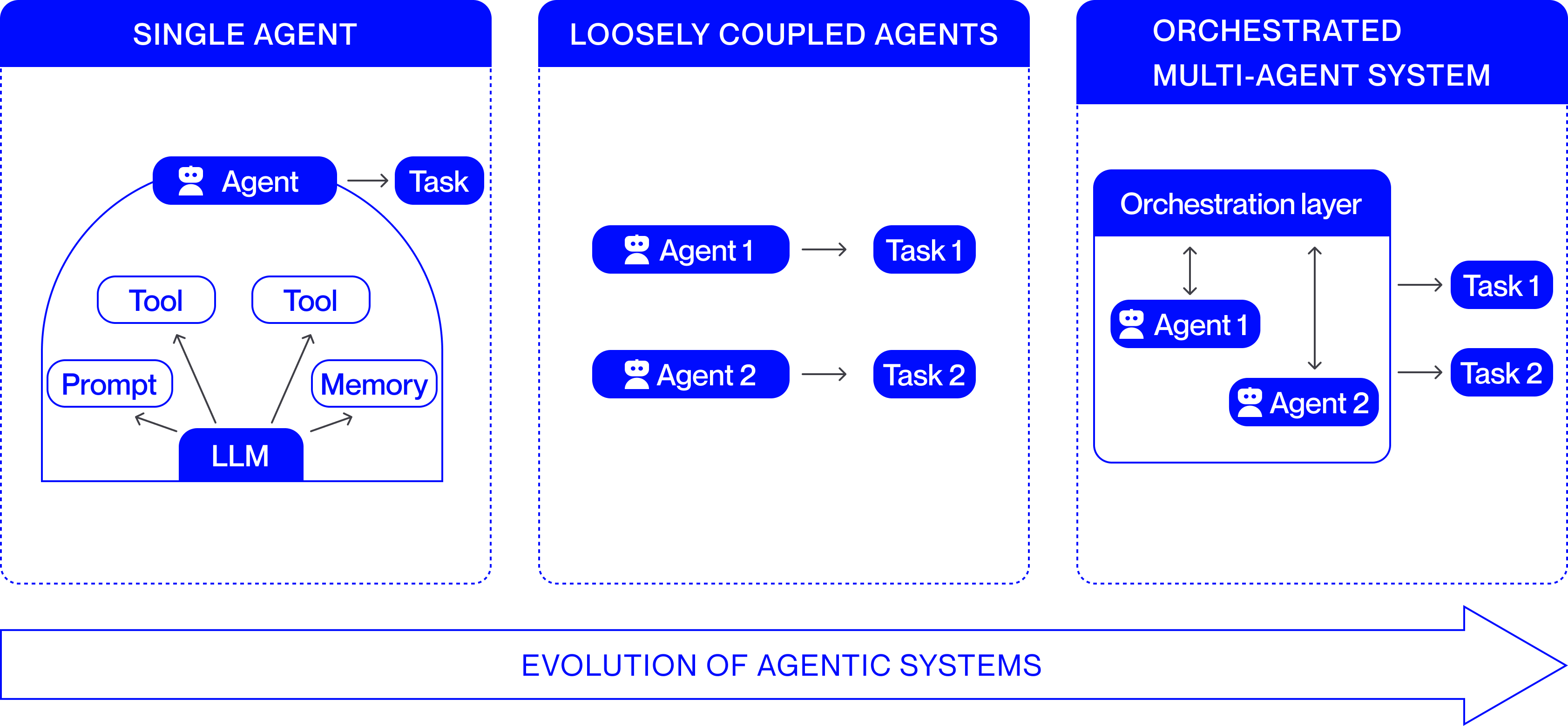
Early deployments relied on single agents. These monolithic systems, with no coordination overhead, were well-suited to narrow tasks such as customer support chatbots that resolve FAQs, financial bots generating daily reports, or personal productivity assistants handling email and calendar management. Their reliability made them effective in bounded contexts, but they lacked scalability and adaptability for complex or dynamic environments.
To address these limitations, research and practice shifted toward loosely coupled agentic systems. In such systems, multiple agents operate in parallel with relative independence, and minimal interaction. This architecture enables specialization and the emergence of collective behaviors that a single agent cannot achieve. Recent examples include scientific research assistants [5] where literature-retrieval, reasoning, and validation agents collaborate to accelerate discovery; collaborative AI coding environments [6] where distinct agents write, review, and test code; news pipelines [7] where aggregation, fact-checking, and synthesis are distributed across agents; and autonomous driving ecosystems [8] where perception, navigation, and coordination agents cooperate loosely to ensure safe operation. Fig. 1 represents the discussed evolution of agentic systems.
<details>
<summary>EvolutionAgenticSystems.png Details</summary>
### Visual Description
## Diagram: Evolution of Agentic Systems
### Overview
The image is a conceptual diagram illustrating three stages in the development of AI agent architectures. It is divided into three vertical panels, each representing a distinct model, arranged from left to right to indicate progression. A large arrow at the bottom reinforces this directional evolution.
### Components/Axes
The diagram is structured into three main panels, each with a blue header:
1. **Left Panel: "SINGLE AGENT"**
* **Central Component:** A large, semi-circular container.
* **Core Engine:** A blue box labeled **"LLM"** (Large Language Model) at the bottom center of the container.
* **Inputs/Components:** Three white boxes with blue borders feed into the LLM:
* **"Prompt"** (left)
* **"Tool"** (center-left)
* **"Tool"** (center-right)
* **"Memory"** (right)
* **Agent & Output:** A blue box with a robot icon labeled **"Agent"** sits atop the container. An arrow points from this Agent box to a blue box labeled **"Task"**.
2. **Center Panel: "LOOSELY COUPLED AGENTS"**
* **Structure:** Two independent, parallel agent-task pairs.
* **First Pair:** A blue box with a robot icon labeled **"Agent 1"** has an arrow pointing to a blue box labeled **"Task 1"**.
* **Second Pair:** A blue box with a robot icon labeled **"Agent 2"** has an arrow pointing to a blue box labeled **"Task 2"**.
* **Relationship:** There is no visual connection or communication line between Agent 1 and Agent 2.
3. **Right Panel: "ORCHESTRATED MULTI-AGENT SYSTEM"**
* **Orchestration Layer:** A large, light-blue container with a dark blue header labeled **"Orchestration layer"**.
* **Agents within Layer:** Inside this container are two blue boxes with robot icons:
* **"Agent 1"** (left)
* **"Agent 2"** (right)
* **Internal Coordination:** Double-headed vertical arrows connect the Orchestration layer header to both Agent 1 and Agent 2, indicating bidirectional communication and control.
* **Output:** Arrows point from the Orchestration layer container to two external blue boxes:
* **"Task 1"** (top)
* **"Task 2"** (bottom)
4. **Bottom Element:**
* A large, horizontal, right-pointing arrow spans the width of the diagram.
* Text inside the arrow reads: **"EVOLUTION OF AGENTIC SYSTEMS"**.
### Detailed Analysis
* **Single Agent Model:** This is a monolithic architecture. A single LLM core is directly augmented with specific capabilities (Tools, Memory) and a Prompt. This unified agent is responsible for executing a single Task.
* **Loosely Coupled Agents Model:** This represents a simple multi-agent setup. Multiple agents (Agent 1, Agent 2) operate independently, each dedicated to its own specific task (Task 1, Task 2). There is no mechanism for coordination or shared context between them.
* **Orchestrated Multi-Agent System Model:** This is a coordinated architecture. A central **Orchestration layer** manages multiple agents (Agent 1, Agent 2). The agents communicate with the orchestration layer (indicated by double-headed arrows), which likely assigns work, manages state, and coordinates their efforts. The system's output (Task 1, Task 2) is a result of this managed collaboration.
### Key Observations
1. **Increasing Complexity:** The diagram shows a clear progression from a single, self-contained unit to multiple independent units, and finally to a managed system of interdependent units.
2. **Introduction of Coordination:** The critical differentiator in the third stage is the **Orchestration layer**. This component is absent in the first two models and is the key enabler for managing complexity and enabling collaboration.
3. **Shift in Responsibility:** In the Single Agent model, the agent is directly responsible for the task. In the Orchestrated model, the agents' primary relationship is with the orchestration layer, which then interfaces with the tasks.
4. **Visual Language:** The use of consistent icons (robot for Agent) and colors (blue for active components) creates clear visual parallels across the three stages, making the evolution easy to follow.
### Interpretation
This diagram illustrates a fundamental trend in the design of AI systems: the move from singular, general-purpose agents toward specialized, collaborative multi-agent systems. The progression suggests that as the complexity of problems or workflows increases, a single agent becomes insufficient. The "Loosely Coupled" stage is a naive multi-agent approach that lacks synergy. The final "Orchestrated" stage represents a mature architecture where a supervisory layer (the Orchestration layer) introduces necessary coordination, communication, and possibly resource management. This allows the system to tackle more complex, multi-faceted tasks (Task 1 & Task 2) that require the combined, coordinated efforts of specialized agents. The diagram argues that orchestration is the key architectural pattern for scaling agentic AI capabilities.
</details>
Figure 1: Evolution of Agentic Systems
## III Architectural Composition of Multi-Agent Systems
Building an orchestrated multi-agent system (MAS) involves more than simply connecting multiple autonomous agents. It requires designing specialized roles, establishing a coordination layer that governs their interactions, and defining clear communication protocols that allow agents to exchange information effectively.
Specialized agents operate as autonomous components that execute well-defined tasks within the system, each contributing a distinct capability toward the collective objective. Their interactions are coordinated through an orchestration layer that determines execution order, manages dependencies, and aligns individual outputs into a coherent operational flow. The exchanges rely on communication protocols that standardize how information is represented and transferred across agents, ensuring semantic consistency and enabling the orchestration layer to maintain synchronized and interpretable system behavior. When these foundational components are applied in practice, they collectively enable complex, domain-specific workflows that require coordinated intelligence across multiple decision points.
The following sections examine these technical elements in greater depth, focusing on agent specialization, orchestration mechanisms, and communication strategies as the foundational components of multi-agent architectures.
## IV Specialized Agents
In a multi-agent system, specialized agents are autonomous components designed to perform narrowly scoped, role-specific tasks within the broader architecture. Each agent typically incorporates a large language model as its cognitive core, enabling it to perceive inputs, reason about them, and act within clearly defined operational boundaries. By assigning distinct roles such as retrieval, reasoning, validation, or monitoring, the system decomposes complex objectives into smaller, coordinated subtasks. This division of labor promotes modularity and collaboration, allowing agents to complement one another’s capabilities, reduce redundancy, and achieve outcomes that surpass those of a single, general-purpose agent. Through such specialization, a multi-agent system attains higher precision, scalability, and robustness while preserving clarity of function and accountability across its components.
Below are the key categories of specialized agents:
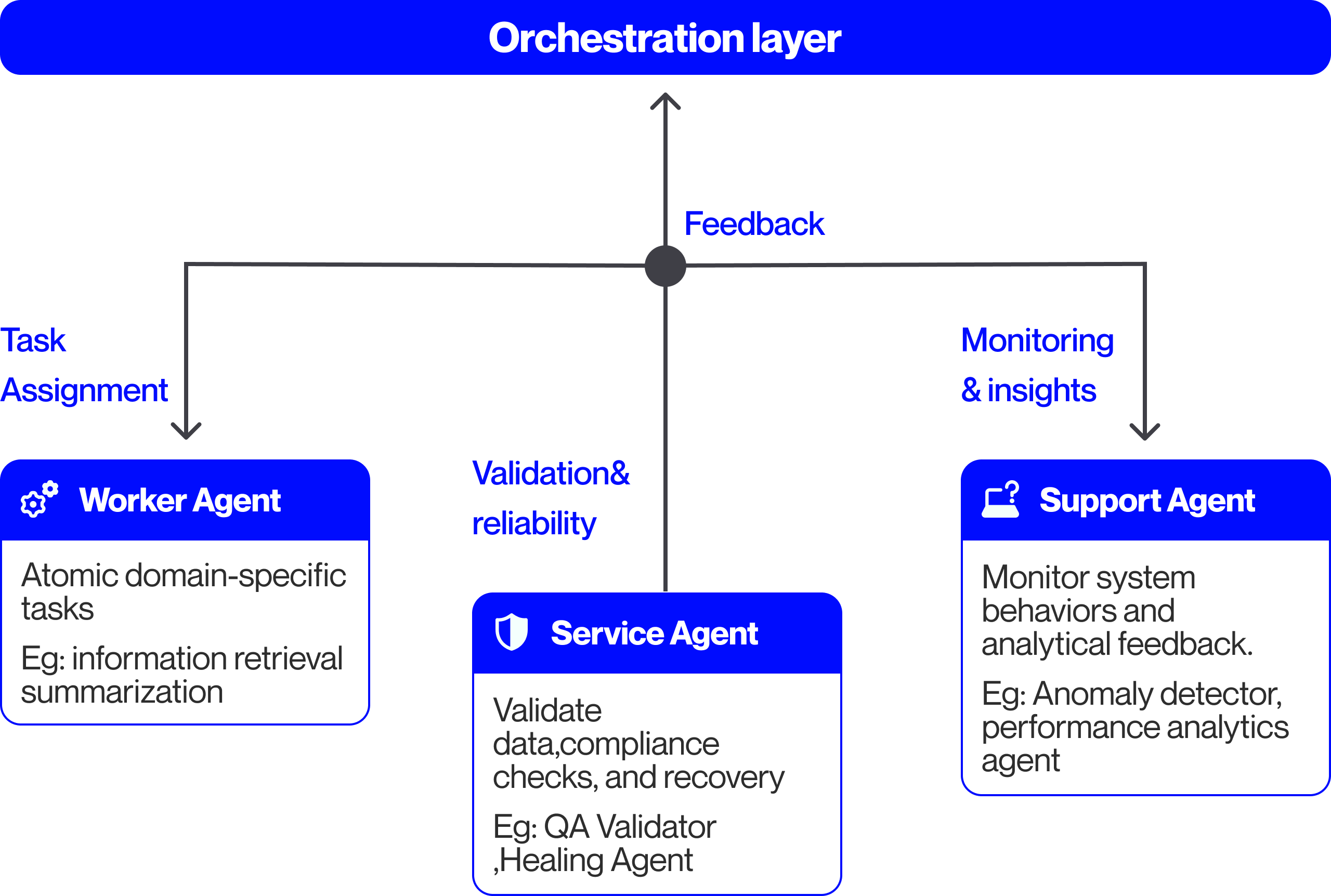
- Worker Agents - Worker agents represent the most basic but essential type. They are responsible for carrying out well-defined tasks such as a Retrieval-augmented generation (RAG) pipeline. In practice, some worker agents are stateless, handling each request independently without retaining context, while others are stateful, tracking progress across multiple steps in a workflow. In large systems, worker agents often operate in parallel, with each specializing in a narrow sub-domain. In a financial underwriting workflow, individual worker agents may extract applicant data from loan documents, compute preliminary credit scores, or generate draft risk assessments that downstream agents validate and consolidate. These agents form the execution layer of the system, performing domain-specific computations that feed subsequent validation and oversight processes.
- Service Agents - Service agents provide shared operational capabilities that other agents depend on during workflow execution. They act as reusable utilities within the multi-agent ecosystem, performing tasks such as quality assurance, compliance enforcement, diagnostics, or automated recovery.
In the context of financial underwriting, quality assurance agents can verify extracted customer data and cross-check it against compliance requirements. Diagnostic agents can inspect inconsistencies or missing data, trace the issues to the responsible module, and generate a structured error report that informs corrective actions. Healing agents can extend this capability by rerunning failed extractions or resetting workflow states to restore normal operation. While healing agents focus on the active system state, upgrade scheduler agents manage version transitions of scoring components and related workflows, ensuring that updates are deployed seamlessly without disrupting ongoing operations.
- Support Agents - Complementing the service agents, support agents operate at a supervisory and analytical level. While service agents provide in-line operational utilities during workflow execution, support agents focus on meta-level oversight by monitoring system behavior, analyzing outcomes, and managing data flows that inform orchestration and optimization. Their function is to maintain the overall health, transparency, and adaptability of the system under varying operational conditions. In the financial underwriting scenario, monitoring agents track decision latency, detect risk model drift, and visualize overall portfolio health for both AI orchestrators and human supervisors. Analytics agents evaluate approval-rate patterns and compliance anomalies, while data agents refresh applicant datasets to maintain currency and accuracy.
<details>
<summary>Specializedagents.png Details</summary>
### Visual Description
\n
## Diagram: Multi-Agent Orchestration Architecture
### Overview
The image is a technical diagram illustrating a hierarchical system architecture centered around an "Orchestration layer." It depicts how this central layer delegates tasks to three specialized agent types and receives feedback from them, forming a closed-loop control system. The design uses a clean, modern aesthetic with blue accent colors for headers and icons against a light gray background.
### Components/Axes
The diagram is structured with a central hub-and-spoke model.
1. **Central Hub (Top Center):**
* **Label:** "Orchestration layer" (white text on a solid blue, rounded rectangle banner spanning the top width).
* **Function:** Acts as the central coordinator and decision-maker.
2. **Communication Node (Center):**
* A solid dark gray circle positioned directly below the "Orchestration layer" banner.
* It serves as the junction point for all communication flows.
3. **Agent Components (Bottom Row, Left to Right):**
* **Worker Agent (Left):**
* **Header:** Blue rounded rectangle with a white gear icon (⚙️) and the text "Worker Agent".
* **Body:** White box with black text: "Atomic domain-specific tasks\nEg: information retrieval summarization".
* **Connection:** A downward-pointing arrow from the central communication node, labeled "Task Assignment" in blue text.
* **Service Agent (Center):**
* **Header:** Blue rounded rectangle with a white shield icon (🛡️) and the text "Service Agent".
* **Body:** White box with black text: "Validate data, compliance checks, and recovery\nEg: QA Validator ,Healing Agent".
* **Connection:** A vertical line connecting it directly to the central communication node, labeled "Validation & reliability" in blue text to its left.
* **Support Agent (Right):**
* **Header:** Blue rounded rectangle with a white icon of a laptop with a question mark (💻❓) and the text "Support Agent".
* **Body:** White box with black text: "Monitor system behaviors and analytical feedback.\nEg: Anomaly detector, performance analytics agent".
* **Connection:** A downward-pointing arrow from the central communication node, labeled "Monitoring & insights" in blue text.
4. **Feedback Loop:**
* A single upward-pointing arrow originates from the central communication node and points to the "Orchestration layer."
* This arrow is labeled "Feedback" in blue text, indicating the flow of information back to the central coordinator.
### Detailed Analysis
The diagram explicitly defines the roles and responsibilities of each agent type through its embedded text:
* **Worker Agent:** Executes discrete, fundamental tasks within a specific domain. Provided examples are "information retrieval" and "summarization."
* **Service Agent:** Focuses on system integrity, performing validation, compliance, and recovery functions. Examples include a "QA Validator" and a "Healing Agent."
* **Support Agent:** Provides oversight and analysis by monitoring system behavior. Examples are an "Anomaly detector" and a "performance analytics agent."
The flow of operations is clearly mapped:
1. The **Orchestration layer** sends directives downward via three channels: "Task Assignment," "Validation & reliability," and "Monitoring & insights."
2. These directives are received by the **Worker Agent**, **Service Agent**, and **Support Agent**, respectively.
3. Information and results from all three agents are aggregated at the central communication node.
4. This aggregated information is sent upward as **Feedback** to the **Orchestration layer**, completing the loop.
### Key Observations
* **Hierarchical Control:** The architecture is strictly top-down for task assignment and bottom-up for feedback, with the Orchestration layer at the apex.
* **Specialization of Labor:** The system is decomposed into three distinct functional categories: execution (Worker), governance (Service), and observation (Support).
* **Closed-Loop System:** The "Feedback" arrow is critical, indicating this is not a fire-and-forget system but one designed for continuous adjustment and learning based on operational data.
* **Self-Healing Implication:** The inclusion of a "Healing Agent" as an example under the Service Agent suggests the architecture is designed for resilience and automated recovery.
### Interpretation
This diagram represents a sophisticated blueprint for a resilient, multi-agent AI or software system. The **Orchestration layer** functions as the "brain," making high-level decisions. The **Worker Agents** are the "hands," performing the actual work. The **Service Agents** act as the "immune system and conscience," ensuring quality, compliance, and integrity. The **Support Agents** serve as the "nervous system and senses," providing the observational data necessary for informed decision-making.
The architecture's core principle is **separation of concerns**, which enhances scalability, maintainability, and reliability. The explicit feedback loop transforms it from a simple command hierarchy into an adaptive system capable of self-optimization. The presence of a "Healing Agent" is particularly notable, moving beyond simple error detection to imply automated remediation—a key characteristic of advanced autonomous systems. This model would be applicable in complex domains like enterprise automation, large-scale AI deployment, or autonomous system management where reliability and continuous operation are paramount.
</details>
Figure 2: Specialized agents in a Multi-Agent System
Fig. 2 summarizes the discussed categories of specialized agents in a multi-agent systems. Across these categories of specialized agents, recent research [9] and enterprise applications demonstrate that coordinated role differentiation significantly enhances the reliability and scalability of multi-agent systems.
## V Orchestration Layer for Coordinated Multi-Agent Operations
The agent orchestration layer forms the control plane of a multi-agent system, transforming autonomous components into a coherent, goal-directed collective. Without orchestration, even highly capable agents risk duplication of effort, logical inconsistency, or unbounded autonomy that diverges from the system’s objectives. It interprets system-level objectives, decomposes them into actionable subtasks, coordinates their execution, and ensures that every output produced aligns with policy, context, and quality requirements.
### V-A Planning and Policy Management
At the heart of the orchestration layer are the planning and policy units, which convert high-level objectives into a structured execution plan.
Their purpose is twofold: the planning unit operates as a goal-decomposition engine that determines what tasks need to be done and in what order, while the policy unit embeds domain and governance constraints to define how these tasks are performed. In a financial underwriting workflow, the planning unit assigns tasks such as data extraction and credit scoring to the corresponding worker agents. The policy unit defines operational and governance constraints and coordinates with the control unit (described in the following subsection) to ensure service agents enforce them throughout execution
Together, they translate abstract goals into a directed execution model that defines who performs which task, in what sequence, under what rules, and with what oversight.
### V-B Execution and Control Management
Once tasks are planned and assigned, the orchestration layer operates as a distributed control system that transitions specialized agents through phases of initialization, execution, validation, and completion.
Here, the execution unit ensures the smooth operation of the designated tasks performed by worker agents and manages telemetry data collection by support agents. The telemetry data is relayed to the control unit, which may delegate remediation or verification tasks to service agents to maintain operational stability. The control unit also manages concurrency and dependency across workflows, allowing parallel execution and synchronization at key checkpoints to preserve consistency. Additionally, it handles task prioritization and dynamic resource allocation to balance throughput, cost, and determinism across varying workloads.
### V-C State and Knowledge Management
For the control unit to achieve synchronization and maintain continuity across workflows, the orchestration layer relies on the state and knowledge management component. This component functions both as a data bus and a knowledge repository.
The state unit manages checkpoints, workflow progress, agent states, and activity logs. Support agents monitor state changes and performance anomalies, while service agents may be invoked to restore checkpoints from the state unit to preserve workflow integrity. The knowledge unit manages contextual and domain-specific information by connecting to external data sources and exposing them as a retrievable context. This ensures that worker agents and orchestration components operate with accurate and aligned information.
This separation of operational state from knowledge state preserves modularity, contextual consistency, and system coherence.
### V-D Quality and Operations Management
Using telemetry, state updates, and contextual data generated by other orchestration units, the quality and operations management component evaluates system performance, validates outcomes, and ensures that orchestrated activities remain compliant and continually optimized. While the control unit focuses on execution stability and the policy unit defines and enforces operational constraints during execution, this component governs verification and optimization of results after execution across the orchestration layer.
The component validates aggregated outputs against defined schemas before integrating them into the shared state, preventing invalid data from propagating through workflows. When inconsistencies or violations are detected, it updates the state accordingly and may invoke service agents to perform diagnostic or remediation actions, ensuring sustained integrity and compliance.
The subsystem also monitors metrics such as latency, throughput, and success rate, using anomaly detection to identify deviations and trigger preemptive interventions. It also supports controlled deployment, testing, and sandboxing new components to maintain stability as agents evolve. Together, these mechanisms ensure resilient, auditable, and continuously improving multi-agent operations.
### V-E Closing Discussion
The orchestration model is exemplified in a financial institution’s credit-risk and fraud detection workflow, where specialized agents are coordinated to ensure consistency and compliance. Incoming loan applications are decomposed by the planning unit into subtasks such as data extraction, risk assessment, compliance review, and fraud screening, while the policy unit embeds governance constraints, including lending regulations and institutional risk thresholds. The execution and control component manages concurrent task execution, collects telemetry, and invokes service agents for recovery when needed. The state and knowledge management component maintains applicant states, historical records, and regulatory references for contextual continuity, while the quality and operations component validates results against policy criteria and applies performance insights to optimize future workflows.
Collectively, these mechanisms show that reliability in multi-agent systems arises not only from intelligent agents but from the orchestration layer that governs planning, execution, and validation, enabling scalable and policy-compliant performance.
## VI Communication Protocols in Orchestrated Systems
Building on the orchestration framework, the agent communication layer operationalizes coordination by enabling agents and external tools to exchange information, control signals, and shared context. While orchestration defines who acts and when, communication ensures those actions remain synchronized and interpretable. Traditional protocols relied on static request–response exchanges and lacked mechanisms for context sharing or policy enforcement. To address these limitations, two emerging standards—the Model Context Protocol (MCP) and Agent-to-Agent (A2A) protocol—establish structured, interoperable communication for tool interaction and peer specialized agentic collaboration. Later subsections explore these protocols in more detail.
### VI-A Model Context Protocol
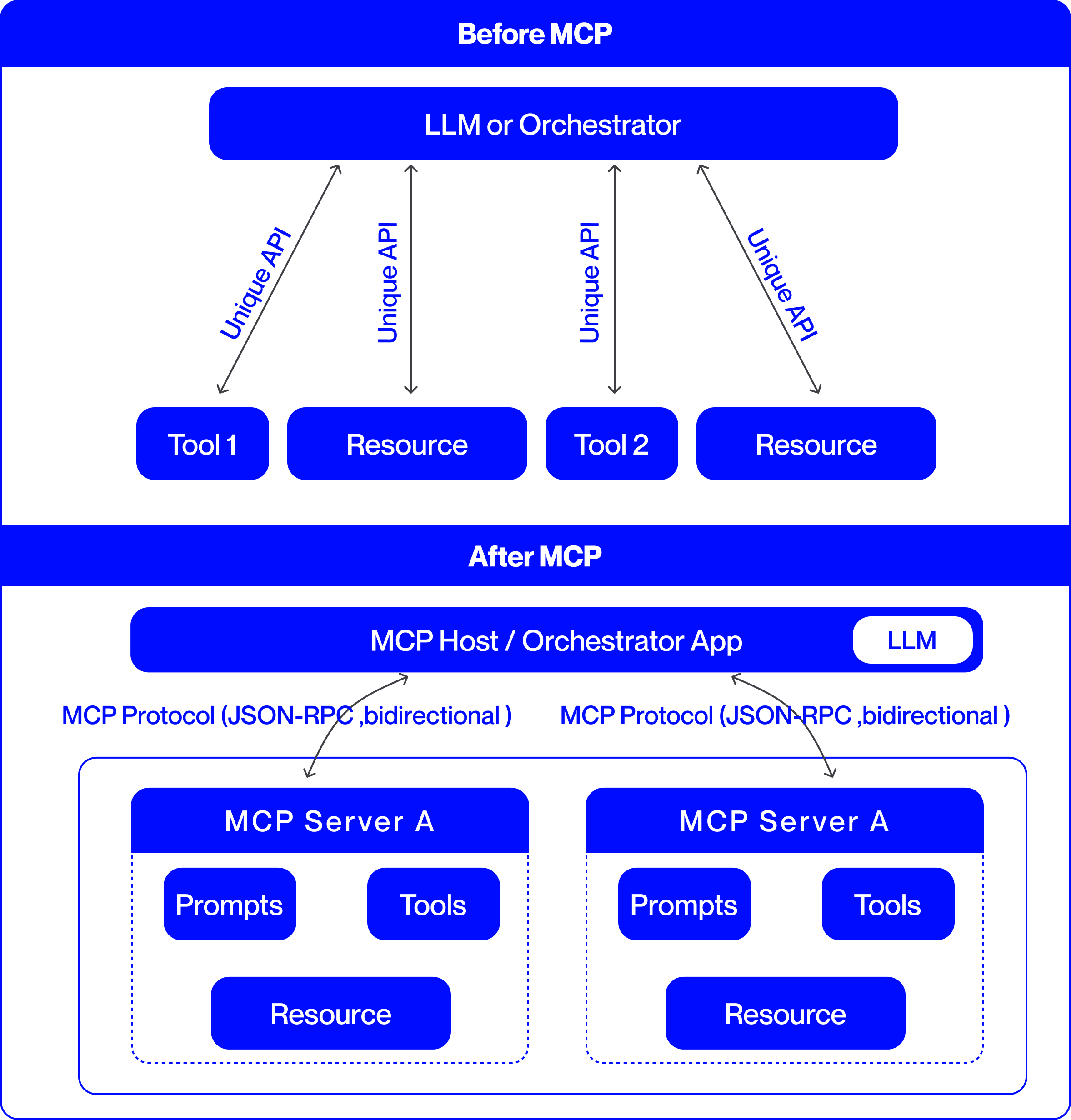
The Model Context Protocol (MCP) [10] provides the standardized communication interface that operationalizes the previously described orchestration flow between agents and external systems like tools, data services, and contextual repositories. As illustrated in Fig. 3, MCP mediates every external invocation through a defined interface that enforces schema consistency, access control, and auditability. This allows the execution unit to dispatch tasks confidently, ensuring that each agent’s external interactions conform to orchestration policies and operational rules.
<details>
<summary>BeforeVSAfter_v3.png Details</summary>
### Visual Description
## System Architecture Diagram: Before and After MCP (Model Context Protocol)
### Overview
This image is a technical comparison diagram illustrating two different architectural approaches for integrating Large Language Models (LLMs) with external tools and resources. The top half is labeled "Before MCP," showing a point-to-point integration model. The bottom half is labeled "After MCP," demonstrating a standardized, protocol-based integration model using the Model Context Protocol (MCP). The diagram uses a consistent color scheme: blue boxes for components and black arrows for connections, set against a light gray background.
### Components/Axes
The diagram is divided into two primary horizontal sections, each with a distinct architecture.
**1. "Before MCP" Section (Top Half):**
* **Central Component:** A large blue rounded rectangle at the top labeled **"LLM or Orchestrator"**.
* **Peripheral Components:** Four smaller blue rounded rectangles arranged horizontally below the central component. From left to right, they are labeled:
* **"Tool 1"**
* **"Resource"**
* **"Tool 2"**
* **"Resource"**
* **Connections:** Four separate, double-headed arrows connect the central "LLM or Orchestrator" to each of the four peripheral components. Each arrow is labeled with the text **"Unique API"**, indicating a custom, point-to-point integration for each tool and resource.
**2. "After MCP" Section (Bottom Half):**
* **Central Component:** A large blue rounded rectangle labeled **"MCP Host / Orchestrator App"**. Embedded within its right side is a smaller white rounded rectangle labeled **"LLM"**.
* **Protocol Layer:** Two curved, double-headed arrows originate from the bottom of the "MCP Host" component. Each arrow is labeled with the text **"MCP Protocol (JSON-RPC, bidirectional)"**.
* **Server Components:** The arrows point to two identical, large blue-outlined containers, each representing an **"MCP Server A"**. The label "MCP Server A" appears in the blue header of each container.
* **Internal Server Components:** Within each "MCP Server A" container, there are three blue rounded rectangles:
* **"Prompts"** (top-left)
* **"Tools"** (top-right)
* **"Resource"** (bottom-center)
### Detailed Analysis
The diagram presents a clear before-and-after narrative focused on system integration complexity.
**"Before MCP" Architecture:**
* **Structure:** A hub-and-spoke model with the "LLM or Orchestrator" at the center.
* **Integration Method:** Each external component (Tool 1, Tool 2, and two Resources) requires a dedicated, custom API connection to the central orchestrator. This is explicitly stated by the four instances of the "Unique API" label.
* **Implication:** This model suggests high maintenance overhead, as each new tool or resource requires building and maintaining a bespoke integration.
**"After MCP" Architecture:**
* **Structure:** A layered, protocol-based model. The "MCP Host / Orchestrator App" (which contains the LLM) acts as a client.
* **Integration Method:** Communication is standardized via the **"MCP Protocol"**, specified as using **JSON-RPC** and being **bidirectional**. This single protocol replaces the multiple "Unique API" connections.
* **Server Abstraction:** Tools, prompts, and resources are now encapsulated within standardized **"MCP Server"** containers (exemplified by "MCP Server A"). The diagram shows two identical servers, implying the architecture supports multiple, interoperable servers.
* **Component Grouping:** Within each server, the diagram groups three key element types: **"Prompts"**, **"Tools"**, and **"Resource"**. This indicates that an MCP server can expose a bundle of related capabilities.
### Key Observations
1. **Standardization vs. Customization:** The most prominent shift is from multiple "Unique API" connections to a single, standardized "MCP Protocol."
2. **Encapsulation:** In the "After" model, tools and resources are no longer standalone entities connected directly to the host. They are encapsulated within "MCP Server" units, which also include "Prompts."
3. **Bidirectional Communication:** The "After" diagram explicitly notes the protocol is "bidirectional," suggesting more interactive communication compared to the implied request-response nature of the "Unique API" arrows.
4. **Scalability Hint:** The presence of two identical "MCP Server A" boxes visually suggests that adding new capabilities involves deploying another standard server, rather than building a new custom API.
### Interpretation
This diagram argues for the adoption of the Model Context Protocol (MCP) as a superior architectural pattern for connecting LLMs to the external world.
* **Problem Demonstrated ("Before"):** The "Before MCP" state represents a fragile and non-scalable integration landscape. Each tool or data source ("Resource") requires custom engineering work ("Unique API"), leading to a combinatorial explosion of connections as the ecosystem grows. This creates maintenance burdens and vendor lock-in.
* **Solution Proposed ("After"):** MCP introduces a standardized interface layer. The "MCP Host" (e.g., an AI application) only needs to implement the MCP client protocol once. Any tool or data source that implements the corresponding MCP server protocol can then connect seamlessly. This decouples the host from the specifics of individual tools.
* **Architectural Benefit:** The model promotes **interoperability** and **modularity**. Developers can create "MCP Servers" that expose specific sets of "Tools," "Prompts," and "Resources." These servers can be developed independently and plugged into any MCP-compatible host. This is analogous to how USB standardized connections for computer peripherals, replacing a multitude of proprietary ports.
* **Underlying Principle:** The diagram illustrates a move from **point-to-point integration** to a **networked protocol-based ecosystem**. This is a common evolution in software architecture to manage complexity and foster innovation, allowing tool creators and application developers to work independently against a shared standard.
</details>
Figure 3: Comparison of agent communication without MCP and with MCP
<details>
<summary>MCP.png Details</summary>
### Visual Description
## Diagram: Model Context Protocol (MCP) Architecture
### Overview
This image is a technical architecture diagram illustrating the structure and data flow of the "Model Context Protocol" (MCP). It depicts a layered system designed to connect AI agents (clients) with external resources (databases, tools, workflows) through a standardized middleware layer. The diagram uses a blue and white color scheme with rounded rectangular boxes for components and arrows to indicate communication flows.
### Components/Flow
The diagram is organized into three primary horizontal layers, stacked vertically.
**1. Header (Top)**
* **Title:** "MODEL CONTEXT PROTOCOL" (centered, bold, blue text).
**2. Main Diagram - Layered Architecture**
The core content is divided into three distinct layers:
* **Layer 1: AGENTIC LAYER (MCP CLIENT)**
* **Position:** Topmost layer, enclosed in a light gray box with a blue header bar.
* **Components:** Two agent icons labeled "Agent A" and "Agent B".
* **Outgoing Flow (Downward Arrow):** Labeled "Structured JSON RPC Calls (via a MCP Client SDK)". This indicates requests sent from agents to the MCP Layer.
* **Incoming Flow (Upward Arrow):** Labeled "Structured JSON Responses". This indicates data returned to the agents.
* **Layer 2: MCP LAYER**
* **Position:** Middle layer, enclosed in a light gray box with a blue header bar.
* **Internal Components (Blue Boxes):**
* "Schema Validator"
* "Session Manger" (Note: Likely a typo for "Manager")
* "Security x access control"
* "Audit logger & versioning"
* "MCP Servers 1"
* "MCP Servers 2"
* "MCP Servers 3"
* **Function:** This layer acts as the protocol's core, handling validation, session management, security, auditing, and hosting multiple server instances.
* **Layer 3: EXTERNAL RESOURCES LAYER**
* **Position:** Bottom layer, enclosed in a light gray box with a blue header bar at the very bottom.
* **Components (Blue Boxes):**
* "DATABASES"
* "TOOLS"
* "WORKFLOWS"
**3. Inter-Layer Communication Flows**
Arrows connect the MCP Servers in the middle layer to the External Resources in the bottom layer, with specific labels for each interaction type:
* **Between "MCP Servers 1" and "DATABASES":**
* Upward Arrow: "Transaction"
* Downward Arrow: "Structured JSON Response"
* **Between "MCP Servers 2" and "TOOLS":**
* Upward Arrow: "Tool invocation"
* Downward Arrow: "Structured JSON Response"
* **Between "MCP Servers 3" and "WORKFLOWS":**
* Upward Arrow: "Workflow Trigger"
* Downward Arrow: "Structured JSON Response"
### Detailed Analysis
The diagram explicitly defines the communication protocol and data structure at each interface:
* **Agent to MCP Layer:** Communication uses "Structured JSON RPC Calls" and receives "Structured JSON Responses".
* **MCP Layer to External Resources:** Each MCP Server instance is specialized for a resource type (Database, Tool, Workflow). The upward calls are specific actions ("Transaction", "Tool invocation", "Workflow Trigger"), while all downward responses are uniformly "Structured JSON Response".
* **Component Hierarchy:** The MCP Layer contains both cross-cutting services (Validator, Session Manager, Security, Logger) and the server instances that interface directly with external resources.
### Key Observations
1. **Standardized Data Format:** The repeated use of "Structured JSON" for all communication flows emphasizes a key design principle of the protocol: using a consistent, machine-readable data format.
2. **Specialization:** The MCP Servers are not generic; they are depicted as specialized endpoints for different external resource categories (Databases, Tools, Workflows).
3. **Security and Audit Focus:** The inclusion of dedicated "Security x access control" and "Audit logger & versioning" components within the MCP Layer highlights these as critical, built-in features of the protocol.
4. **Potential Typo:** The component "Session Manger" is likely intended to be "Session Manager".
### Interpretation
This diagram presents the Model Context Protocol as a structured middleware solution for AI agent interoperability. It solves the problem of connecting diverse AI agents (Agent A, Agent B) to a heterogeneous set of external systems (data, tools, processes) by:
* **Abstracting Complexity:** Agents make simple RPC calls via an SDK, unaware of the underlying resource specifics.
* **Enforcing Standards:** The MCP Layer mandates a JSON-based communication schema, validated by the "Schema Validator".
* **Centralizing Governance:** Critical functions like security, access control, auditing, and session management are centralized within the MCP Layer, providing a single point for policy enforcement and monitoring.
* **Enabling Scalability:** The presence of multiple "MCP Servers" suggests the architecture can scale horizontally to handle load or separate concerns.
The flow is strictly hierarchical and mediated: Agents never communicate directly with Databases, Tools, or Workflows. All interaction is brokered, validated, and logged by the MCP Layer, positioning it as a crucial control plane for secure and manageable AI agent operations.
</details>
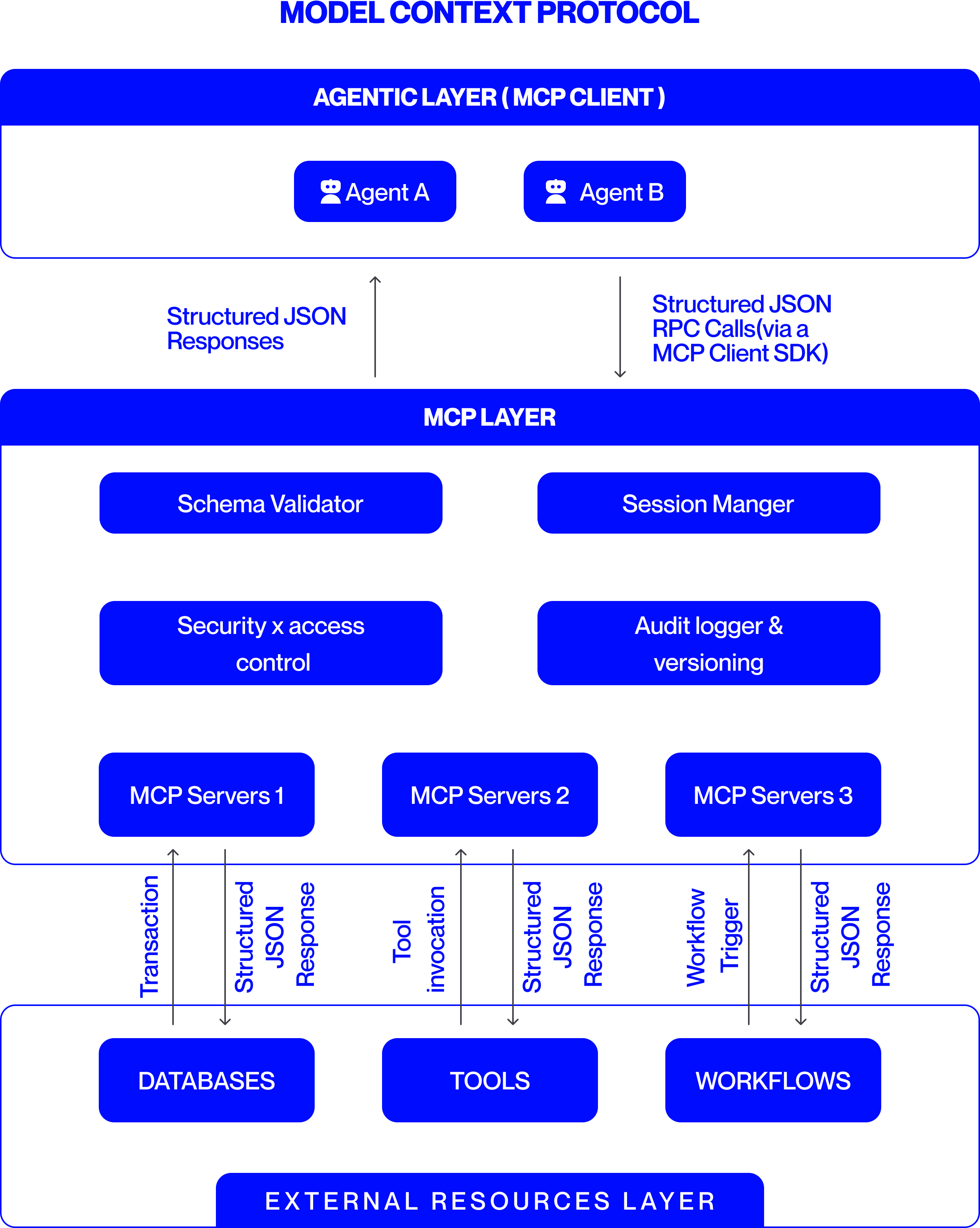
Figure 4: Integration of the MCP within the orchestration architecture
Within the orchestration architecture, MCP follows a client–server design in which agents or orchestrators act as clients that request external capabilities such as tools, resources, or prompts, while connected systems expose these as standardized, callable services. Through MCP, the planning and control units translate defined tasks into executable tool calls and govern how and when agents access these resources in compliance with policy constraints. MCP’s session management supports both stateless and stateful exchanges, allowing context continuity across multi-step workflows. These exchanges are logged and synchronized with orchestration state, enabling the state and knowledge management component to maintain consistency and allowing the quality and operations component to verify compliance and alignment with expected results.
As shown in Fig. 4, MCP functions as the operational bridge between high-level orchestration plans and low-level tool execution. It converts planned objectives into structured, policy-aligned invocations and feeds execution data back into orchestration memory and quality loops. Extensions such as ScaleMCP [11] dynamically synchronize tool inventories across agents, while AgentMaster [12] integrates MCP with inter-agent communication frameworks such as A2A to support multimodal collaboration and information retrieval within orchestrated multi-agent systems.
### VI-B Agent-to-Agent Protocol
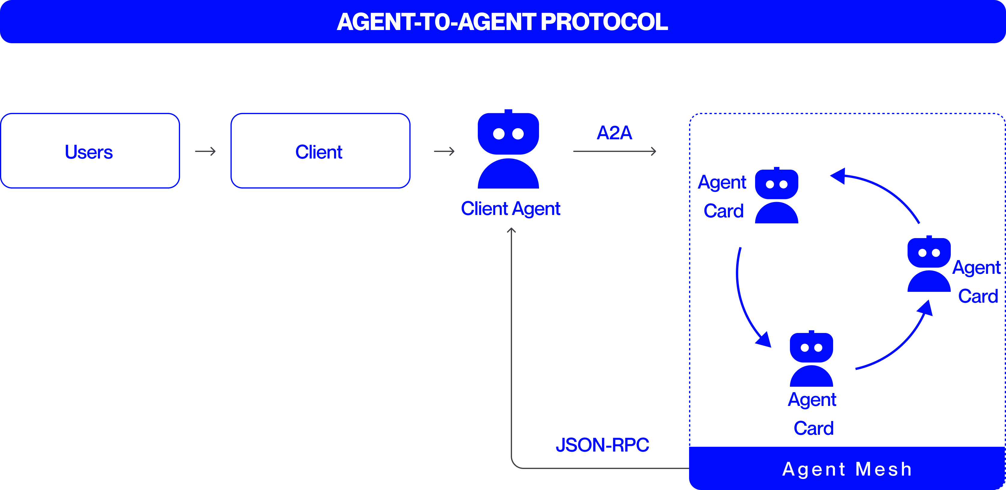
While MCP governs how agents interact with tools and data, the Agent-to-Agent (A2A) protocol [13] defines standardized communication amongst specialized agents themselves. It supports negotiation, delegation, and coordination across distributed ecosystems while maintaining interoperability, traceability, and security [14]. Together, MCP and A2A form the dual foundation of agent communication—MCP for tool access and A2A for peer collaboration (Fig. 5).
<details>
<summary>A2A.png Details</summary>
### Visual Description
## Diagram: Agent-to-Agent Protocol Flow
### Overview
The image is a technical diagram illustrating the "AGENT-TO-AGENT PROTOCOL." It depicts a linear flow from a user to a client, then to a client agent, which communicates with a mesh of interconnected agents. The diagram uses a clean, blue-and-white color scheme with icons and labeled boxes to represent entities and arrows to indicate the direction of communication or data flow.
### Components/Axes
The diagram is structured from left to right, with the following labeled components:
1. **Header (Top):** A solid blue bar spanning the width of the image containing the title text in white, bold, uppercase letters: **"AGENT-TO-AGENT PROTOCOL"**.
2. **Left Section (Initiation Flow):**
* A rounded rectangle labeled **"Users"**.
* A right-pointing arrow (`→`).
* A rounded rectangle labeled **"Client"**.
* A right-pointing arrow (`→`).
* A blue robot icon labeled **"Client Agent"**.
3. **Central Connection:**
* A right-pointing arrow originating from the "Client Agent" icon, labeled above with the text **"A2A"**.
4. **Right Section (Agent Mesh):**
* A large, dashed-line rectangle with a solid blue footer bar labeled **"Agent Mesh"**.
* Inside this rectangle, three identical blue robot icons are arranged in a triangular/circular pattern. Each is labeled **"Agent Card"**.
* Curved blue arrows connect these three "Agent Card" icons in a clockwise cycle, indicating bidirectional or peer-to-peer communication within the mesh.
5. **Feedback Loop:**
* A thin, black line originates from the bottom of the "Agent Mesh" rectangle, travels left, then upward, ending with an arrow pointing to the bottom of the "Client Agent" icon.
* This line is labeled with the text **"JSON-RPC"**.
### Detailed Analysis
* **Flow Direction:** The primary flow is linear and left-to-right: `Users → Client → Client Agent → (via A2A) → Agent Mesh`.
* **Agent Mesh Internal Flow:** Within the "Agent Mesh," the three "Agent Card" agents are interconnected in a closed loop, suggesting a network where any agent can communicate with any other.
* **Protocol Labels:**
* **"A2A"**: This label on the arrow from "Client Agent" to the "Agent Mesh" likely stands for "Agent-to-Agent," the core protocol being illustrated.
* **"JSON-RPC"**: This label on the feedback line indicates the communication protocol or data format used for responses or data sent from the Agent Mesh back to the Client Agent.
* **Spatial Grounding:** The "Agent Mesh" is positioned on the right side of the diagram, enclosed in its own dashed boundary. The "Client Agent" is centrally located, acting as the gateway between the client-side flow and the agent network. The "JSON-RPC" feedback line runs along the bottom of the diagram.
### Key Observations
1. **Hierarchical Entry Point:** The system has a clear entry point (Users) that funnels through a single Client and Client Agent before accessing the distributed agent network.
2. **Decentralized Mesh:** The "Agent Mesh" is depicted as a peer-to-peer network without a central coordinator, as shown by the circular communication arrows between the three "Agent Card" nodes.
3. **Asymmetric Communication:** The initial request ("A2A") and the response/feedback ("JSON-RPC") are shown as separate pathways, suggesting a request-response pattern where the mesh's reply uses a specific RPC protocol.
4. **Abstraction of Agents:** The agents within the mesh are uniformly labeled "Agent Card," implying they are standardized, interchangeable units or instances within the network.
### Interpretation
This diagram outlines a protocol architecture for enabling complex tasks by delegating work from a user-facing client to a network of specialized agents.
* **What it demonstrates:** It shows how a single client agent can interface with a decentralized swarm of agents. The "Client Agent" acts as a proxy or orchestrator, translating the user's request (via the Client) into the "A2A" protocol to engage the mesh. The mesh agents collaborate amongst themselves (circular arrows) to process the task.
* **How elements relate:** The flow establishes a clear separation of concerns: the user/client layer handles initiation and presentation, the Client Agent manages protocol translation and session management, and the Agent Mesh performs distributed computation or task execution. The "JSON-RPC" return path is critical, as it closes the loop, allowing results from the mesh to be sent back to the originating client agent.
* **Notable implications:** The design suggests scalability (more agents can be added to the mesh) and robustness (no single point of failure within the mesh). The use of "Agent Card" might imply that each agent has a defined interface or capability profile. The protocol aims to abstract the complexity of multi-agent coordination away from the end-user and client application.
</details>
Figure 5: Agent-to-Agent Protocol
Through A2A, worker agents can delegate subtasks or share intermediate results, service agents can communicate diagnostic information or recovery status, and support agents can broadcast telemetry or performance insights that inform collective progress. This peer-level exchange ensures that task dependencies are dynamically managed and that agents can resolve interdependencies without requiring centralized intervention. The control unit supervises these interactions to ensure policy alignment and to maintain synchronization with the broader orchestration plan, while communication records are captured within the state and knowledge management component for traceability and recovery.
A2A employs a peer communication model either direct or mediated through the orchestrator, enabling reliable, authenticated message exchange. Each message carries structured metadata and standardized payloads, ensuring consistency across heterogeneous implementation. Robust security controls, including cryptographic signing and role-based routing, guarantee message integrity and policy compliance.
Although peer-oriented, A2A remains supervised by the orchestration layer, which validates and synchronizes exchanges to maintain coherence with global workflows. Emerging research explores scalable and hybrid architectures that combine A2A and MCP for multimodal, adaptive coordination in enterprise-grade agentic systems.
## VII Safety, Governance and Observability
Ensuring the reliability of multi-agent systems depends on safeguards embedded within orchestration and communication mechanisms. Within the orchestration layer, the control and quality and operations management units enforce safety and governance through validation, monitoring, and recovery mechanisms that maintain compliance and operational integrity. Similarly, MCP and A2A protocols embed protective measures such as schema validation, authenticated exchanges, and access control to ensure secure and interpretable communication. Core guardrails mitigate hallucinations and enforce consistency checks to prevent agents from producing unsafe or conflicting outputs. These protections are reinforced by internal audits, event logging, and least-privilege policies that promote transparency, accountability, and traceability across the system. Privacy constraints restrict agents to sharing only task-relevant information. Continuous monitoring, carried out through support agents and the quality and operations management unit, tracks latency, throughput, and correctness to evaluate performance and detect drift. Together, these practices transform multi-agent systems from experimental collectives into dependable, auditable, and continually improving infrastructures that balance autonomy with control.
<details>
<summary>MASArchitecture.png Details</summary>
### Visual Description
## Diagram: Multi-Agent System Architecture
### Overview
This image is a technical architecture diagram illustrating the structure and components of a "Multi-Agent System." It depicts a layered design with an Orchestration Layer overseeing an Agent Studio, which contains multiple interacting agents. The system connects to external resources and includes governance components. The diagram uses a consistent visual language: blue rounded rectangles for components, white text for labels, and black arrows to indicate communication or control flows.
### Components/Axes
The diagram is organized into distinct regions and components:
**1. Title:**
* **Text:** "MULTI-AGENT SYSTEM ARCHITECTURE"
* **Position:** Centered at the very top of the image.
**2. Orchestration Layer:**
* **Position:** A large, light-gray container spanning the top width of the diagram, directly below the title.
* **Label:** "ORCHESTRATION LAYER" (white text on a blue header bar).
* **Sub-Components (from left to right):**
* "Planning & policies"
* "Runtime & Resources"
* "State & Knowledge Mgmt"
* "Quality & Operations"
* "Observability Tools"
* **Connections:** Three vertical, downward-pointing arrows originate from the first three sub-components ("Planning & policies", "Runtime & Resources", "State & Knowledge Mgmt") and point into the central "Agent Studio" container.
**3. Agent Studio:**
* **Position:** The central, largest light-gray container in the diagram.
* **Label:** "Agent Studio" (white text on a blue footer bar at the bottom of this container).
* **Internal Components (Agents):**
* **Agent 1:** A blue box in the upper-left. Contains a white sub-box with a robot icon and the label "Worker".
* **Agent 2:** A blue box in the center. Contains a white sub-box with a robot icon and the label "Service".
* **Agent 3:** A blue box in the lower-right. Contains a white sub-box with a robot icon and the label "Helper".
* **Internal Connections (A2A):**
* A double-headed arrow labeled "A2A" connects Agent 1 and Agent 2.
* A double-headed arrow labeled "A2A" connects Agent 2 and Agent 3.
* A curved, single-headed arrow points from Agent 1 to Agent 3.
**4. External Resources (Right Side):**
* **Position:** A vertical stack of three blue boxes to the right of the Agent Studio.
* **Components (from top to bottom):**
* **Toolkit:** A blue box with a dotted-line inner container holding two smaller blue boxes, each labeled "Tool".
* **Shared Memory & Database:** A solid blue box.
* **External API's:** A solid blue box.
* **Connections (MCP):** Three double-headed horizontal arrows, each labeled "MCP", connect the Agent Studio container to each of these three external resource boxes.
**5. Governance & Safety (Bottom):**
* **Position:** Two blue boxes below the Agent Studio container.
* **Components (from left to right):**
* "Audits Traceability"
* "Guard Rails"
* **Connections:** Two single-headed, downward-pointing arrows originate from the "Agent Studio" footer bar and point to these two boxes.
### Detailed Analysis
* **Flow and Hierarchy:** The primary control flow is top-down from the Orchestration Layer to the Agent Studio. The agents within the studio communicate laterally via "A2A" (Agent-to-Agent) protocols. The entire Agent Studio interacts with external systems (Tools, Memory, APIs) via "MCP" (likely Model Context Protocol or a similar interconnect standard).
* **Agent Roles:** The agents are specialized: "Worker" (Agent 1), "Service" (Agent 2), and "Helper" (Agent 3). Their positioning suggests a potential workflow or hierarchy, with Agent 1 at the top-left initiating actions.
* **Visual Coding:** All primary components are blue. The Orchestration Layer and Agent Studio are defined by light-gray background containers. Communication protocols are explicitly labeled on the arrows ("A2A", "MCP").
### Key Observations
1. **Centralized Orchestration:** The system is explicitly managed by a dedicated Orchestration Layer with clear functional divisions (planning, runtime, state, quality, observability).
2. **Agent Specialization:** The three agents are not generic; they have distinct roles (Worker, Service, Helper), implying a division of labor.
3. **Standardized Interfaces:** Communication is formalized through named protocols ("A2A" for inter-agent, "MCP" for agent-to-resource), suggesting a modular and interoperable design.
4. **Integrated Governance:** "Audits Traceability" and "Guard Rails" are first-class components connected directly to the Agent Studio, highlighting the importance of safety, monitoring, and compliance in the system's design.
5. **Resource Abstraction:** External tools, memory, and APIs are abstracted behind a consistent "MCP" interface, simplifying agent development.
### Interpretation
This diagram outlines a robust, enterprise-grade architecture for deploying collaborative AI agents. It moves beyond a simple agent loop to a managed ecosystem.
* **What it demonstrates:** The architecture separates concerns effectively. The **Orchestration Layer** acts as the "brain" or control plane, handling meta-tasks like planning, resource allocation, and quality control. The **Agent Studio** is the "execution plane" where specialized agents perform concrete tasks, collaborating via A2A. The right-side components represent the **"resource plane,"** providing persistent memory, tools, and external connectivity. The bottom components form the **"governance plane,"** ensuring actions are traceable and safe.
* **Relationships:** The Orchestration Layer supervises but does not micromanage the agents. The agents are peers that collaborate. They rely on external resources but access them through a unified protocol (MCP), which promotes loose coupling. The governance components are sinks for logs and enforcers of constraints, receiving data from the agent execution environment.
* **Notable Implications:** The inclusion of "State & Knowledge Mgmt" in the orchestration layer and "Shared Memory" as a resource suggests a strong emphasis on maintaining context and long-term knowledge across agent interactions. The "A2A" protocol is critical, as it enables complex, multi-step problem-solving that a single agent could not handle. This architecture is designed for scalability, maintainability, and operational rigor, suitable for complex, real-world automation tasks where reliability and oversight are paramount.
</details>
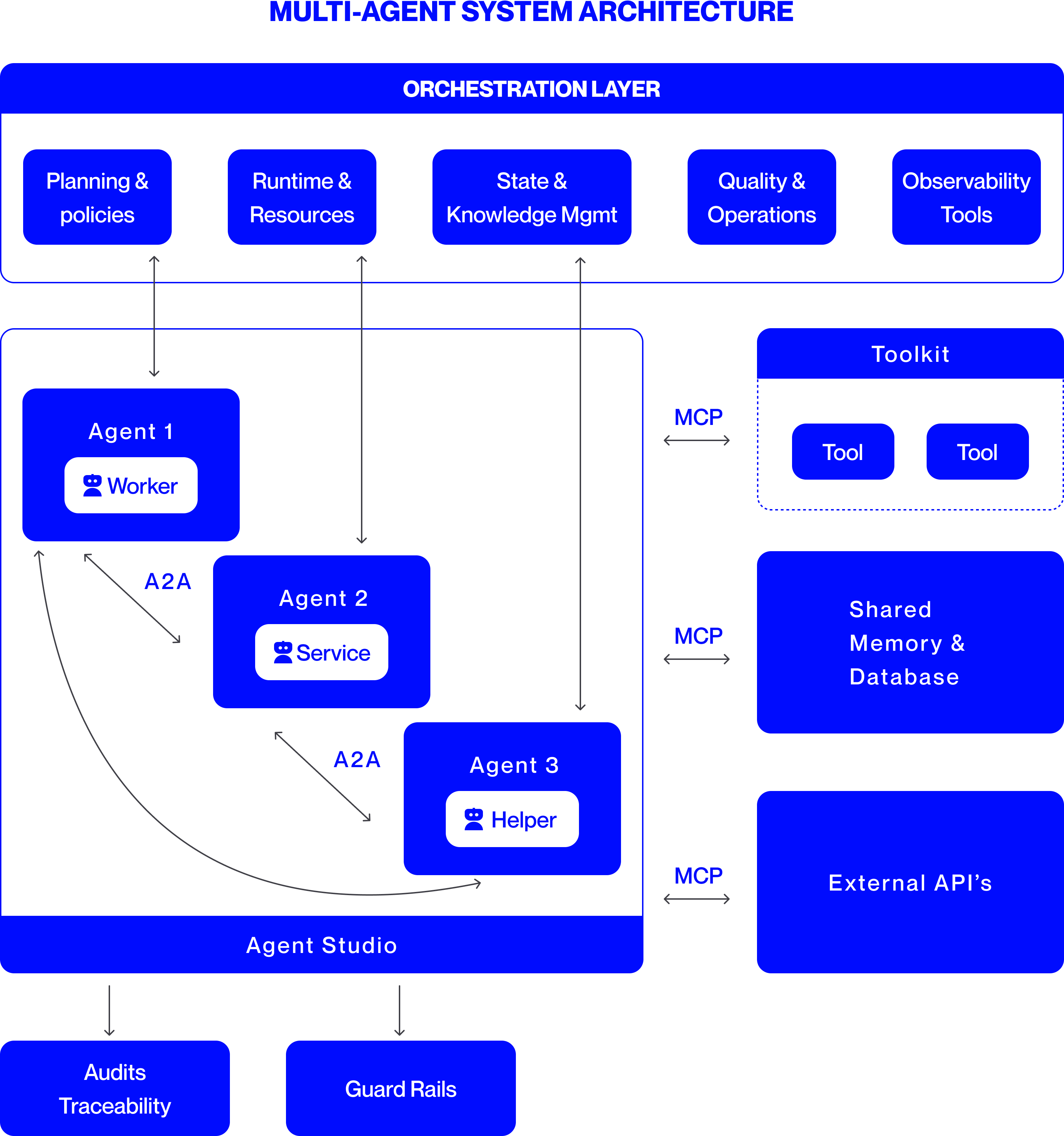
Figure 6: Orchestrated Multi-Agent System Architecture
To summarize, the overall architecture of an orchestrated multi-agent system is shown in Fig. 6. The architecture integrates all core components that enable coordination, communication, and governance across distributed agents. At its foundation are specialized agent types, interacting through standardized protocols such as MCP for tool and data access and A2A for inter-agent collaboration. The orchestration layer oversees planning, execution, and quality control, while observability and governance modules ensure reliability, compliance, and transparency. Together, these elements form a cohesive, scalable framework that operationalizes autonomous intelligence under structured orchestration.
## VIII Case Studies
### VIII-A Banking, Financial Services and Insurance
Multi-agent AI systems are revolutionizing Banking, Financial Services, and Insurance (BFSI) industry by delivering dramatic efficiency gains and ROI. Insurers are deploying networks of specialized AI agents to automate the labor-intensive underwriting process. For example, autonomous agents studied in [15] now parse insurance applications and supporting documents with over 95% accuracy, enabling much faster policy issuance. In another use-case explored in [15], a mortgage lender integrated Document AI and Decision AI agents to handle loan paperwork, achieving a 20× faster approval process while cutting processing costs by 80%. Similarly, [16] presents a multi-agent automation framework for property claims underwriting, where specialized agents collaborate to evaluate claim documents, assess damage estimates, and validate policy conditions. Such multi-agent systems clearly outperform both manual processes and single-agent automation, delivering a strong value proposition in BFSI.
### VIII-B Software Engineering and IT Modernization
Multi-agent systems are also proving their worth in software engineering. A large bank recently applied an agentic AI “digital factory” [17] to modernize its legacy core software, which comprised hundreds of applications. Different agents took on specialized coding tasks: one agent automatically documented existing legacy code, another generated new code modules, others reviewed code written by their peers, and additional agents integrated and tested these modules. This multi-agent architecture allows parallel execution and continuous code quality checks, reducing the coordination burdens that slowed the purely human teams. In practice, this approach led to over a 50% reduction in development time and effort for early-adopter teams at the bank.
### VIII-C Cross Industry Adoption
The success of multi-agent AI is spurring widespread adoption across industries. In customer service, companies are reimagining call centers with agentic AI: instead of just assisting human representatives, agents autonomously handle routine inquiries and issues. Studies suggest that up to 80% of common support incidents could be resolved by AI agents without human intervention, cutting resolution times by 60–90% in fully agent-driven workflows. Meanwhile, sectors like healthcare are exploring multi-agent setups where one agent analyzes patient symptoms or medical literature and another suggests treatment plans, all under a doctor’s supervision. From finance and insurance to software development, legal research, and healthcare, multi-agent systems are being rapidly embraced as organizations recognize their measurable performance advantages over manual or single-agent approaches.
## IX Challenges, Risks and Future Research
As multi-agent systems scale, key challenges emerge around efficiency, cost, and governance. Coordination among numerous agents can create communication overhead, message congestion, and performance bottlenecks unless workflows are carefully managed. The cost of adoption remains significant, enterprises must invest in orchestration software, skilled engineering teams, and continuous monitoring infrastructure to ensure reliability and compliance. Governance presents another difficulty, as decentralized autonomy complicates oversight and accountability. Risks inherited from large language models, such as hallucination, bias, and data leakage, are magnified when agents interact, raising safety, ethical, and privacy concerns that demand rigorous evaluation and control frameworks.
Future research focuses on making orchestration smarter, safer, and more adaptive. Hybrid and federated designs aim to balance centralized control with decentralized flexibility, while semantic orchestration seeks to match tasks dynamically with the most capable agents. Advances in federated learning and cross-domain collaboration promise secure knowledge sharing without exposing raw data. Standardized benchmarks, simulation testbeds, and open-source orchestration frameworks will further enable transparent performance comparison and lower entry barriers. Together, these directions move multi-agent systems toward scalable, accountable, and trustworthy deployment across enterprise and societal domains.
## X Conclusion
Agentic systems have evolved from single agents that perform narrow tasks, to loosely coupled multi-agent setups, and now to orchestrated collectives where coordination ensures consistency, scale, and reliability. Recent advances show that orchestrated systems are not only viable but already delivering value in real deployments, from BFSI claims processing and fraud detection to healthcare diagnostics and software engineering. Benchmarks and case studies demonstrate measurable gains in productivity, error reduction, and scalability compared with manual or single-agent approaches.
Looking forward, enterprises are moving toward dynamic ecosystems where agents can form, dissolve, and reorganize in response to tasks, much like human teams. To realize this vision, the community must invest in open protocols for interoperability, standardized benchmarks, and shared research infrastructure. With these foundations, orchestrated multi-agent systems can mature into a reliable and adaptable backbone for enterprise intelligence at scale.
## References
- [1] Z. Hou, J. Tang, and Y. Wang, “HALO: Hierarchical Autonomous Logic-Oriented Orchestration for Multi-Agent LLM Systems,” arXiv:2505.13516, 2025. [Online]. Available: https://arxiv.org/abs/2505.13516.
- [2] Y. Dang, C. Qian, X. Luo, J. Fan, Z. Xie, R. Shi, W. Chen, C. Yang, X. Che, Y. Tian, X. Xiong, L. Han, Z. Liu, and M. Sun, “Multi-Agent Collaboration via Evolving Orchestration,” arXiv:2505.19591, 2025. [Online]. Available: https://arxiv.org/abs/2505.19591.
- [3] PwC, “PwC launches AI Agent Operating System for enterprises,” PwC US Newsroom, Press Release, Mar. 18, 2025. [Online]. Available: https://www.pwc.com/us/en/about-us/newsroom/press-releases/pwc-launches-ai-agent-operating-system-enterprises.html. Accessed: Oct. 9, 2025.
- [4] Accenture, “Accenture Introduces Trusted Agent Huddle to Allow Seamless, First-of-its-Kind, Multi-System AI Agent Collaboration Across the Enterprise,” Accenture Newsroom, Jan. 21, 2025. [Online]. .
- [5] R. Deng, M. Zhao, X. Zheng, H. Guo, and Z. Jin, “Agent Laboratory: Using LLM Agents as Research Assistants,” arXiv:2501.04227, 2025. doi: 10.48550/arXiv.2501.04227. [Online]. Available: https://arxiv.org/abs/2501.04227.
- [6] S. Luo, Y. Xu, H. Zhang, and K. Zhang, “AgentCoder: Multi-Agent Code Generation with Effective Testing and Self-optimisation,” arXiv:2312.13010, 2023. doi: 10.48550/arXiv.2312.13010. [Online]. Available: https://arxiv.org/abs/2312.13010.
- [7] Y. Lin, J. Park, X. Li, and S. Zhang, “Multi-Agent Fact Checking,” arXiv:2503.02116, 2025. doi: 10.48550/arXiv.2503.02116. [Online]. Available: https://arxiv.org/abs/2503.02116.
- [8] Z. Zhao, Y. Sun, H. Wu, L. Zhang, and Y. Li, “KoMA: Knowledge-driven Multi-agent Framework for Autonomous Driving with Large Language Models,” arXiv:2407.14239, 2024. doi: 10.48550/arXiv.2407.14239. [Online]. Available: https://arxiv.org/abs/2407.14239.
- [9] Y. Fu, H. Sun, Y. Song, J. Liu, X. Chen, Z. Zhang, J. Tang, and T.-S. Chua, “A Survey on Agentic Large Language Models: Architecture, Capabilities, and Applications,” arXiv preprint arXiv:2402.01680, 2024. [Online]. Available: https://arxiv.org/abs/2402.01680. Accessed: Nov. 17, 2025.
- [10] Model Context Protocol, “What is the Model Context Protocol (MCP)?,” Documentation, 2025. [Online]. Available: https://modelcontextprotocol.io/docs/getting-started/intro. Accessed: Oct. 9, 2025.
- [11] E. Lumer, A. Gulati, V. K. Subbiah, P. H. Basavaraju, and J. A. Burke, “ScaleMCP: Dynamic and Auto-Synchronizing Model Context Protocol Tools for LLM Agents,” arXiv:2505.06416, 2025. doi: 10.48550/arXiv.2505.06416. [Online]. Available: https://arxiv.org/abs/2505.06416.
- [12] C. C. Liao, D. Liao, and S. S. Gadiraju, “AgentMaster: A Multi-Agent Conversational Framework Using A2A and MCP Protocols for Multimodal Information Retrieval and Analysis,” arXiv:2507.21105, 2025. doi: 10.48550/arXiv.2507.21105. [Online]. Available: https://arxiv.org/abs/2507.21105.
- [13] A. Chawla, “A Visual Guide to Agent2Agent (A2A) Protocol,” Daily Dose of Data Science (Substack), Apr. 16, 2025. [Online]. Available: https://blog.dailydoseofds.com/p/a-visual-guide-to-agent2agent-a2a. Accessed: Oct. 9, 2025.
- [14] The Linux Foundation (A2A Project), “Agent2Agent (A2A) Protocol — Latest Documentation,” 2025. [Online]. Available: https://a2a-protocol.org/latest/. Accessed: Oct. 9, 2025.
- [15] B. Pazur, “17 Useful AI Agent Case Studies,” Multimodal.dev (blog), May 14, 2025. [Online]. Available: https://www.multimodal.dev/post/useful-ai-agent-case-studies. Accessed: Oct. 9, 2025.
- [16] M. I. Sajid, “Multi-Agentic Automation for Evaluating Property Claims in Underwriting,” Open Journal of Applied Sciences, vol. 15, no. 4, pp. 819–833, Apr. 2025. doi: 10.4236/ojapps.2025.154055. [Online]. Available: https://www.scirp.org/journal/paperinformation?paperid=141685.
- [17] A. Sukharevsky, D. Kerr, K. Hjartar, L. Hämäläinen, S. Bout, and V. Di Leo, “Seizing the agentic AI advantage,” McKinsey & Company (QuantumBlack) report, Jun. 13, 2025. [Online]. Available: https://www.mckinsey.com/capabilities/quantumblack/our-insights/seizing-the-agentic-ai-advantage. Accessed: Oct. 9, 2025.