# REASON: Accelerating Probabilistic Logical Reasoning for Scalable Neuro-Symbolic Intelligence
**Authors**: Zishen Wan, Che-Kai Liu, Jiayi Qian, Hanchen Yang, Arijit Raychowdhury, Tushar Krishna
## Abstract
Neuro-symbolic AI systems integrate neural perception with symbolic and probabilistic reasoning to enable data-efficient, interpretable, and robust intelligence beyond purely neural models. Although this compositional paradigm has shown superior performance in domains such as mathematical reasoning, planning, and verification, its deployment remains challenging due to severe inefficiencies in symbolic and probabilistic inference. Through systematic analysis of representative neuro-symbolic workloads, we identify probabilistic logical reasoning as the inefficiency bottleneck, characterized by irregular control flow, low arithmetic intensity, uncoalesced memory accesses, and poor hardware utilization on CPUs and GPUs.
This paper presents REASON, an integrated acceleration framework for probabilistic logical reasoning in neuro-symbolic AI. At the algorithm level, REASON introduces a unified directed acyclic graph representation that captures common structure across symbolic and probabilistic models, coupled with adaptive pruning and regularization. At the architecture level, REASON features a reconfigurable, tree-based processing fabric optimized for irregular traversal, symbolic deduction, and probabilistic aggregation. At the system level, REASON is tightly integrated with GPU streaming multiprocessors through a programmable interface and multi-level pipeline that efficiently orchestrates neural, symbolic, and probabilistic execution. Evaluated across six neuro-symbolic workloads, REASON achieves 12-50 $\times$ speedup and 310-681 $\times$ energy efficiency over desktop and edge GPUs under TSMC 28 nm node. REASON enables real-time probabilistic logical reasoning, completing end-to-end tasks in 0.8 s with 6 mm ${}^{\text{2}}$ area and 2.12 W power, demonstrating that targeted acceleration of probabilistic logical reasoning is critical for practical and scalable neuro-symbolic AI and positioning REASON as a foundational system architecture for next-generation cognitive intelligence.
## I Introduction
Large Language Models (LLMs) have demonstrated remarkable capabilities in natural language understanding, image recognition, and complex pattern learning from vast datasets [23, 46, 42, 16]. However, despite their success, LLMs often struggle with factual accuracy, hallucinations, multi-step reasoning, and interpretability [35, 62, 2, 61]. These limitations have spurred the development of compositional AI systems, which integrate neural with symbolic and probabilistic reasoning to create robust, transparent, and intelligent cognitive systems. footnotetext: † Corresponding author
One promising compositional paradigm is neuro-symbolic AI, which integrates neural, symbolic, and probabilistic components into a unified cognitive architecture [60, 1, 72, 9, 75]. In this system, the neural module captures the statistical, pattern-matching behavior of learned models, performing rapid function approximation and token prediction for intuitive perception and feature extraction. The symbolic and probabilistic modules perform explicit, verifiable reasoning that is structured, interpretable, and robust under uncertainty, managing logic-based reasoning and probabilistic updates. This paradigm integrates intuitive generalization and deliberate reasoning.
Neuro-symbolic AI has demonstrated superior abstract deduction, complex question answering, mathematical reasoning, logical reasoning, and cognitive robotics [28, 66, 55, 81, 12, 38, 41, 71]. Its ability to learn efficiently from fewer data points, produce transparent and verifiable outputs, and robustly handle uncertainty and ambiguity makes it particularly advantageous compared to purely neural approaches. For example, recently Meta’s LIPS [28] and Google’s AlphaGeometry [66] leverage compositional neuro-symbolic approaches to solve complex math problems and achieve a level of human Olympiad gold medalists. R 2 -Guard [20] leverages LLM and probabilistic models to improve robust reasoning capability and resilience against jailbreaks. They represent a paradigm shift for AI that requires robust, verifiable, and explainable reasoning.
Despite impressive algorithmic advances in neuro-symbolic AI – often demonstrated on large-scale distributed GPU clusters – efficient deployment at the edge remains a fundamental challenge. Neuro-symbolic agents, particularly in robotics, planning, interactive cognition, and verification, require real-time logical inference to interact effectively with physical environments and multi-agent systems. For example, Ctrl-G, a text-infilling neuro-symbolic agent [83], must execute hundreds of reasoning steps per second to remain responsive, yet current implementations take over 5 minutes on a desktop GPU to complete a single task. This latency gap makes practical deployment of neuro-symbolic AI systems challenging.
To understand the root causes of this inefficiency, we systematically analyze a diverse set of neuro-symbolic workloads and uncover several system- and architecture-level challenges. Symbolic and probabilistic kernels frequently dominate end-to-end runtime and exhibit highly irregular execution characteristics, including heterogeneous compute patterns and memory-bound behavior with low ALU utilization. These kernels suffer from limited exploitable parallelism and irregular, uncoalesced memory accesses, leading to poor performance and efficiency on CPU and GPU architectures.
To address these challenges, we develop an integrated acceleration framework, REASON, which to the best of our knowledge, is the first to accelerate probabilistic logical reasoning-based neuro-symbolic AI systems. REASON is designed to close the efficiency gap of compositional AI by jointly optimizing algorithms, architecture, and system integration for the irregular and heterogeneous workloads inherent to neuro-symbolic reasoning.
At the algorithm level, REASON introduces a unified directed acyclic graph (DAG) representation that captures shared computational structure across symbolic and probabilistic kernels. An adaptive pruning and regularization technique further reduces model size and computational complexity while preserving task accuracy. At the architecture level, REASON features a flexible design optimized for various irregular symbolic and probabilistic computations, leveraging the unified DAG representation. The architecture comprises reconfigurable tree-based processing elements (PEs), compiler-driven workload mapping, and memory layout to enable highly parallel and energy-efficient symbolic and probabilistic computation. At the system level, REASON is tightly integrated with GPU streaming multiprocessors (SMs), forming a heterogeneous system with a programmable interface and multi-level execution pipeline that efficiently orchestrates neural, symbolic, and probabilistic kernels while maintaining high hardware utilization and scalability as neuro-symbolic models evolve. Notably, unlike conventional tree-like computing arrays optimized primarily for neural workloads, REASON provides reconfigurable support for neural, symbolic, and probabilistic kernels within a unified execution fabric, enabling efficient and scalable neuro-symbolic AI systems.
This paper, therefore, makes the following contributions:
- We conduct a systematic workload characterization of representative logical- and probabilistic-reasoning-based neuro-symbolic AI models, identifying key performance bottlenecks and architectural optimization opportunities (Sec. II, Sec. III).
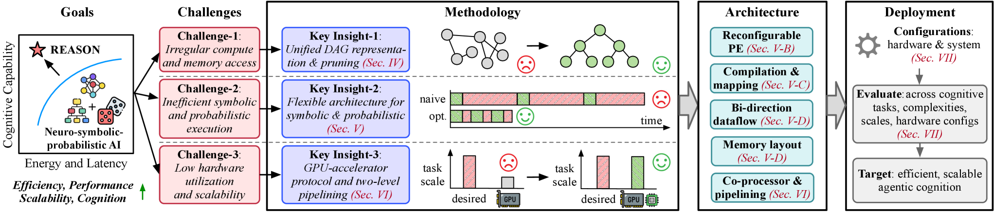
- We propose REASON, an integrated co-design framework, to efficiently accelerate probabilistic logical reasoning in neuro-symbolic AI, enabling practical and scalable deployment of compositional intelligence (Fig. 4).
- REASON introduces cross-layer innovations spanning (i) a unified DAG representation with adaptive pruning at the algorithm level (Sec. IV), (ii) a reconfigurable symbolic/probabilistic architecture and compiler-driven dataflow and mapping at the hardware level (Sec. V), and (iii) a programmable system interface with a multi-level execution pipeline at the system level (Sec. VI) to improve neuro-symbolic efficiency.
- Evaluated across cognitive tasks, REASON enables flexible support for symbolic and probabilistic operations, achieving 12-50 $\times$ speedup and 310-681 $\times$ energy efficiency compared to desktop and edge GPUs. REASON enables fast and efficient logical and probabilistic reasoning in 0.8 s per task with 6 mm 2 area and 2.12 W power consumption. (Sec. VII).
## II Neuro-Symbolic AI Systems
This section presents the preliminaries of neuro-symbolic AI with its algorithm flow (Sec. II-A), scaling performance analysis (Sec. II-B), and key computational primitives (Sec. II-C).
<details>
<summary>x1.png Details</summary>
### Visual Description
## Diagram: Conceptual Architecture of Neuro-Symbolic AI
### Overview
The image presents a conceptual framework for "Neuro-Symbolic" artificial intelligence. It contrasts "Neuro" systems (Neural Networks/Large Language Models) with "Symbolic" systems (Logical and Probabilistic reasoning). The diagram illustrates how these two paradigms interact and provides specific application examples showing a three-stage workflow (Neuro $\rightarrow$ Logical $\rightarrow$ Probabilistic).
### Components/Axes
#### 1. Architecture Diagram (Top Section)
* **Neuro (Left):** A pink-shaded box labeled "Neuro". Inside is the text "DNN/LLM (Fast Thinking)" accompanied by a neural network node-and-link icon.
* **Symbolic (Center):** A white box with a black border containing two stacked sub-components:
* **Logical (Slow Thinking):** A green-shaded box with a tree-structure icon.
* **Probabilistic (Bayesian Thinking):** A blue-shaded box with a dice icon.
* **Interaction:** Two vertical arrows between the Logical and Probabilistic boxes indicate bidirectional communication.
* **Symbolic Expansion (Right):** A large light-green area expanding from the "Symbolic" block, detailing the mathematical/logical foundations:
* **First-Order Logic (FOL) Boolean Satisfiability (SAT):** A logic gate diagram with inputs $X_1, X_2, X_3, X_4$ and outputs $Y_1, Y_2$, utilizing intersection ($\cap$), union ($\cup$), and negation ($\neg$) operators.
* **Probabilistic Circuit (PC):** A tree diagram with nodes labeled $f$, $+$, and $\times$, processing inputs $X_1, X_2, X_3, X_4$.
* **Hidden Markov Model (HMM):** A sequence diagram showing states $S_1 \to S_2 \to S_3 \dots$ with corresponding inputs $X_1, X_2, X_3$.
#### 2. Application Examples (Bottom Section)
A table-like structure listing five domains. Each row follows a three-stage pipeline:
* **Stage 1 (Pink background):** Neural/Feature extraction phase.
* **Stage 2 (Green background):** Logical/Reasoning phase.
* **Stage 3 (Blue background):** Probabilistic/Inference phase.
| Category | Stage 1 (Neuro) | Stage 2 (Logical) | Stage 3 (Probabilistic) |
| :--- | :--- | :--- | :--- |
| **Commonsense Reason** | feature extraction | rule logic | uncertainty infer. |
| **Cognitive Robotics** | scene graph | logic-based planning | uncertainty infer. |
| **Medical Diagnosis** | feature extraction | rule reasoning | likelihood infer. |
| **Question Answering** | parsing | symbolic query planning | missing fact infer. |
| **Math Solving** | initial sol. gen. | algebra solver | uncertainty infer. |
*(Note: "infer." is an abbreviation for "inference".)*
### Detailed Analysis
* **Neuro vs. Symbolic:** The diagram explicitly maps "Neuro" to "Fast Thinking" (intuitive, pattern-based) and "Symbolic" to "Slow Thinking" (deliberative, rule-based).
* **Symbolic Sub-types:** The "Symbolic" block is bifurcated into "Logical" (deterministic, rule-based) and "Probabilistic" (stochastic, Bayesian). The expansion on the right confirms that "Symbolic" AI in this context encompasses both discrete logic (FOL/SAT) and probabilistic models (PC/HMM).
* **Workflow Consistency:** Across all five application examples, the pipeline is consistent:
1. **Input/Extraction:** The "Neuro" component handles the raw data (parsing, feature extraction, scene graph generation).
2. **Processing:** The "Logical" component performs the heavy lifting (rule logic, planning, algebra solving).
3. **Output/Refinement:** The "Probabilistic" component handles the final output, specifically dealing with "uncertainty," "likelihood," or "missing facts."
### Key Observations
* **Color Coding:** The diagram uses a consistent color scheme: Pink for Neuro/Input, Green for Logical/Processing, and Blue for Probabilistic/Inference. This color coding is applied consistently across the architecture diagram and the application examples.
* **The "Neuro" Bottleneck:** The arrow pointing from the "Neuro" block to the "Symbolic" block suggests that the Neuro component acts as the front-end or "perception" layer for the Symbolic component.
* **Uncertainty Handling:** In 3 out of 5 application examples (Commonsense, Robotics, Math), the final stage is "uncertainty infer." This highlights that the primary role of the Probabilistic component is to manage the ambiguity inherent in the outputs of the Logical component.
### Interpretation
This diagram illustrates the **Neuro-Symbolic AI paradigm**, which seeks to combine the strengths of Deep Learning (DNN/LLM) with the strengths of Classical AI (Logic/Probability).
* **The "Why":** Deep Learning models (Neuro) are excellent at pattern recognition but struggle with reasoning, consistency, and explaining their decisions. Symbolic systems are excellent at reasoning but struggle with raw, unstructured data.
* **The Synthesis:** The diagram demonstrates a "System 1" (Fast) and "System 2" (Slow) architecture. The Neuro component acts as the "System 1" (intuitive, fast, feature extraction), while the Symbolic component acts as the "System 2" (deliberative, logical, planning).
* **Peircean Investigative View:** The flow suggests that the "Symbolic" block is the "interpreter" of the "Neuro" block. The Neuro block provides the *signs* (features/data), and the Symbolic block provides the *interpretants* (logic/rules/probability). The inclusion of "Probabilistic" alongside "Logical" acknowledges that real-world reasoning is rarely purely binary; it requires a bridge between rigid logic and the messy, uncertain nature of the real world. The diagram essentially argues that for AI to reach human-level reasoning, it must move beyond pure pattern matching and incorporate structured, probabilistic, and logical frameworks.
</details>
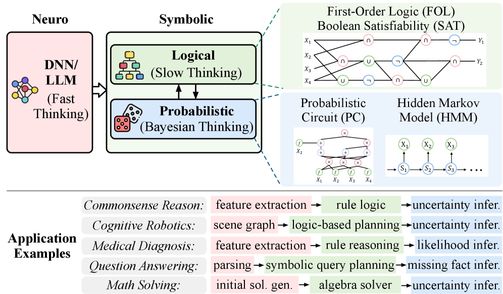
Figure 1: Neuro-symbolic algorithmic flow and operations. The neural module serves as a perceptual and intuitive engine for representation learning, while the symbolic module performs structured logical reasoning with probabilistic inference. This compositional pipeline enables complex cognitive tasks across diverse scenarios.
### II-A Neuro-Symbolic Cognitive Intelligence
LLMs and DNNs excel at natural language understanding and image recognition. However, they remain prone to factual errors, hallucinations, challenges in complex multi-step reasoning, and vulnerability to out-of-distribution or adversarial inputs. Their black-box nature also impedes interpretability and formal verification, undermining trust in safety-critical domains. These limitations motivate the development of compositional systems that integrate neural models with symbolic and probabilistic reasoning to achieve greater robustness, transparency, and intelligence.
Neuro-symbolic AI represents a paradigm shift toward more integrated and trustworthy intelligence by combining neural, symbolic, and probabilistic techniques. This hybrid approach has shown superior performance in abstract deduction [81, 12], complex question answering [38, 41], and logical reasoning [66, 55]. By learning from limited data and producing transparent, verifiable outputs, neuro-symbolic systems provide a foundation for cognitive intelligence. Fig. 1 presents a unified neuro-symbolic pipeline, illustrating how its components collaborate to solve complex tasks.
<details>
<summary>x2.png Details</summary>
### Visual Description
This image contains four distinct charts, labeled (a) through (d), analyzing the performance and efficiency of various AI models across different tasks.
## Multi-Panel Chart: Scaling Performance and Efficiency Analysis
### Overview
The image is a composite of four sub-charts. Panels (a), (b), and (c) display "Task Accuracy vs. Model Size" for three different categories of reasoning tasks. Panel (d) displays "Task Runtime vs. Complexity" for International Math Olympiad problems. The charts compare different model sizes (7B, 8B, 13B, 70B, GPT) and different reasoning methodologies (denoted by (C) and (M) in the legends).
### Components/Axes
**Panels (a), (b), and (c):**
* **X-Axis:** Model Size, with categories: 7B, 8B, 13B, 70B, GPT.
* **Y-Axis:** Task Accuracy (%), ranging from 20% to 100% (or 30% to 90% in panel c).
* **Legends:**
* **(a) Complex Reasoning Tasks:**
* Textedit (C) [Blue Square], Textedit (M) [Grey Square]
* CLUTRR (C) [Orange Triangle], CLUTRR (M) [Grey Triangle]
* ProofWriter (C) [Green Circle], ProofWriter (M) [Grey Circle]
* **(b) Math Reasoning Tasks:**
* GSM8K (C) [Blue Square], GSM8K (M) [Grey Square]
* SVAMP (C) [Orange Triangle], SVAMP (M) [Grey Triangle]
* TabMWP (C) [Green Circle], TabMWP (M) [Grey Circle]
* In-Domain GSM8K (C) [Red Diamond]
* In-Domain MATH (C) [Purple Diamond]
* **(c) Question-Answering Tasks:**
* AmbigNQ (C) [Blue Square], AmbigNQ (M) [Grey Square]
* TriviaQA (C) [Orange Triangle], TriviaQA (M) [Grey Triangle]
* HotpotQA (C) [Green Circle], HotpotQA (M) [Grey Circle]
**Panel (d):**
* **X-Axis:** Inter. Math Olympics reasoning (Year_Problem), with categories: 00_P1, 08_P6, 04_P1, 12_P5, 20_P6, 19_P6.
* **Y-Axis:** Task runtime (min), ranging from 0 to 30.
* **Legend:**
* Neuro-symbolic models (AlphaGeometry) [Blue Circle]
* RL-based CoT reasoning models [Grey Circle]
---
### Detailed Analysis
#### Panel (a): Complex Reasoning Tasks
* **Trend:** All (C) series show a general upward trend as model size increases. The (M) series are consistently lower than their (C) counterparts and show flatter growth.
* **Data Points:**
* At 7B, accuracy ranges from ~20% (ProofWriter M) to ~85% (Textedit C).
* At GPT, accuracy ranges from ~40% (Textedit M) to ~95% (ProofWriter C).
#### Panel (b): Math Reasoning Tasks
* **Trend:** High variance in performance. (C) variants generally outperform (M) variants. The In-Domain (C) models (Red and Purple diamonds) show the highest performance at the 70B and GPT levels.
* **Data Points:**
* At 7B, accuracy is clustered between ~10% and ~55%.
* At GPT, accuracy is clustered between ~25% and ~95%.
#### Panel (c): Question-Answering Tasks
* **Trend:** All series show a clear, consistent upward slope from 7B to GPT.
* **Data Points:**
* At 7B, accuracy ranges from ~30% (HotpotQA M) to ~65% (AmbigNQ C).
* At GPT, accuracy ranges from ~55% (HotpotQA M) to ~90% (AmbigNQ C).
#### Panel (d): Scaling Efficiency Analysis
* **Trend:** Both model types show an upward slope, indicating that as problem complexity increases (left to right), runtime increases.
* **Data Points:**
* **Neuro-symbolic models (Blue):** Starts at ~7 minutes (00_P1) and rises steadily to ~13 minutes (19_P6).
* **RL-based CoT models (Grey):** Starts at ~12 minutes (00_P1) and rises more steeply to ~29 minutes (19_P6).
---
### Key Observations
1. **Methodology Gap:** In panels (a), (b), and (c), the (C) variants (likely Chain-of-Thought) consistently outperform the (M) variants across all model sizes.
2. **Scaling Returns:** Increasing model size generally correlates with higher task accuracy, though the rate of improvement varies by task type.
3. **Efficiency Divergence:** In panel (d), the gap between the Neuro-symbolic models and RL-based CoT models widens as the complexity of the math problems increases. The Neuro-symbolic approach is significantly more efficient (faster) than the RL-based CoT approach.
### Interpretation
The data demonstrates a clear hierarchy in performance based on methodology: the (C) variants are superior to (M) variants for reasoning tasks. Furthermore, the charts suggest that while scaling model size (up to GPT) improves accuracy, it does not eliminate the performance gap between different task types or methodologies.
Panel (d) provides a critical insight into the trade-offs of AI reasoning: while RL-based CoT models are a common approach, they are computationally more expensive (slower) than Neuro-symbolic models like AlphaGeometry. As problem complexity increases, the RL-based models' runtime grows significantly faster than the Neuro-symbolic models, suggesting that Neuro-symbolic architectures may be more scalable for high-complexity reasoning tasks where time efficiency is a constraint.
</details>
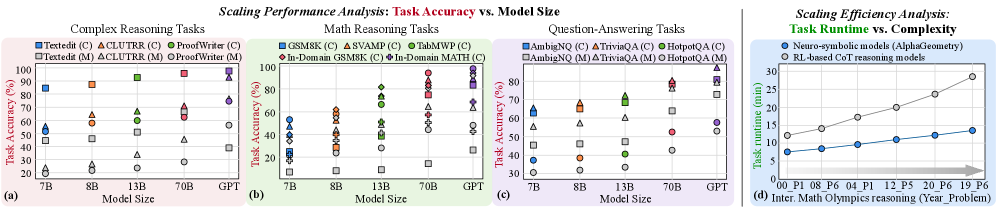
Figure 2: Scaling performance and efficiency. (a)-(c) Task accuracy of compositional LLM-symbolic models (C) and monolithic LLMs (M - shown in gray) across model sizes on complex reasoning, mathematical reasoning, and question-answering tasks. (d) Runtime efficiency comparison between LLM-symbolic models and RL-based CoT models on mathematical reasoning tasks [76].
Neural module. The neural module serves as the perceptual and intuitive engine, typically DNN or LLM, excelling at processing high-dimensional sensory inputs (e.g., images, audio, text) and converting them into feature representations. It handles perception, feature extraction, and associative learning, providing the abstractions needed for higher-level cognition.
Symbolic module. The symbolic module is the logical core operating on neural abstractions and includes symbolic and probabilistic operations. Logical components apply formal logic, rules, and ontologies for structured reasoning and planning, enabling logically sound solutions. Probabilistic components manage uncertainty by representing knowledge probabilistically, supporting belief updates and decision-making under ambiguity, reflecting a nuanced reasoning model.
Together, these modules form a complementary reasoning hierarchy. Neural module captures statistical, pattern-matching behavior of learned models, producing rapid but non-verifiable outputs (Fast Thinking), while symbolic modules perform explicit, verifiable reasoning that is structured and reliable (Slow Thinking). The probabilistic module complements both and enables robust planning under ambiguity (Bayesian Thinking). This framework integrates intuitive generalization with deliberate reasoning.
### II-B Scaling Performance Analysis of Neuro-Symbolic Systems
Scaling performance analysis. Neuro-symbolic AI systems exhibit superior reasoning capability and scaling behavior compared to monolithic LLMs on complex tasks. We compare representative neuro-symbolic systems against monolithic LLMs across complex reasoning, mathematical reasoning, and question-answering benchmarks (Fig. 2 (a)-(c)). The results reveal two advantages. First, higher accuracy: compositional neuro-symbolic models consistently outperform monolithic LLMs of comparable size. Second, improved scaling efficiency: smaller neuro-symbolic models are sufficient to match or exceed the performance of significantly larger closed-source LLMs. Together, these results highlight the potential scaling limitations of monolithic LLMs and the efficiency benefits of compositional neuro-symbolic reasoning.
Comparison with RL-based reasoning models. Beyond monolithic LLMs, recent advancements in reinforcement learning (RL) and chain-of-thought (CoT) prompting improve LLM reasoning accuracy but incur significant computational and scalability overheads (Fig. 2 (d)). First, computational cost: RL-based reasoning often requires hundreds to thousands of LLM queries per decision step, resulting in prohibitively high inference latency and energy consumption. Second, scalability: task-specific fine-tuning constrains generality, whereas neuro-symbolic models use symbolic and probabilistic reasoning modules or tools without retraining. Fig. 2 (d) reveals that neuro-symbolic models AlphaGeometry [66] achieve over $2\times$ efficiency gains and superior data efficiency compared to CoT-based LLMs on mathematical reasoning tasks.
### II-C Computational Primitives in Neuro-Symbolic AI
We identify the core computational primitives that are commonly used in neuro-symbolic AI systems (Fig. 1). While neural modules rely on DNNs or LLMs for perception and representation learning, the symbolic and probabilistic components implement structured reasoning. In particular, logical reasoning is typically realized through First-Order Logic (FOL) and Boolean Satisfiability (SAT), probabilistic reasoning through Probabilistic Circuits (PCs), and sequential reasoning through Hidden Markov Models (HMMs). Together, these primitives form the algorithmic foundation of neuro-symbolic systems that integrate learning, logic, and uncertainty-aware inference.
First-Order Logic (FOL) and Boolean Satisfiability (SAT). FOL provides a formal symbolic language for representing structured knowledge using predicates, functions, constants, variables and quantifiers ( $\forall,\exists$ ), combined with logical connectives. For instance, the statement “every student has a mentor” can be expressed as $\forall x\bigl(\mathrm{Student}(x)\to\exists y\,(\mathrm{Mentor}(y)\wedge\mathrm{hasMentor}(x,y))\bigr)$ , where predicates encode properties and relations over domain elements. FOL semantics map symbols to domain objects and relations, enabling precise and interpretable logical reasoning. SAT operates over propositional logic and asks whether a conjunctive normal form (CNF) formula $\varphi=\bigwedge_{i=1}^{m}\Bigl(\bigvee_{j=1}^{k_{i}}l_{ij}\Bigr)$ admits a satisfying assignment, where each literal $l_{ij}$ is a Boolean variable or its negation. Modern SAT solvers extend the DPLL algorithm with conflict-driven clause learning (CDCL), incorporating non-chronological backtracking and clause learning to improve scalability [40, 33]. Cube-and-conquer further parallelizes search by splitting into “cube” DPLL subproblems and concurrent CDCL “conquer” solvers [13, 67]. Together, FOL’s expressive representations and SAT’s solving mechanisms form the logic backbone of neuro-symbolic systems, enabling exact logical inference alongside neural learning.
| Representative Neuro- Symbolic Workloads | AlphaGeometry [66] | R 2 -Guard [20] | GeLaTo [82] | Ctrl-G [83] | NeuroPC [6] | LINC [52] | |
| --- | --- | --- | --- | --- | --- | --- | --- |
| Deployment Scenario | Application | Math theorem proving & reasoning | Unsafety detection | Constrained text generation | Interactive text editing, text infilling | Classification | Logical reasoning, Deductive reasoning |
| Advantage vs. LLM | Higher deductive reasoning, higher generalization | Higher LLM resilience, higher data efficiency, effective adaptability | Guaranteed constraint satisfaction, higher generalization | Guaranteed constraints satisfaction, higher generalization | Enhanced interpretability, theoretical guarantee | Higher precision, reduced overconfidence, higher scalability | |
| Computation Pattern | Neural | LLM | LLM | LLM | LLM | DNN | LLM |
| Symbolic | First-order logic, SAT solver, acyclic graph | First-order logic, probabilistic circuit, Hidden Markov model | First-order logic, SAT solver, Hidden Markov model | Hidden Markov model, probabilistic circuits | First-order logic, probabilistic circuit | First-order logic, solver | |
TABLE I: Representative neuro-symbolic workloads. Selected neuro-symbolic workloads used in our analysis, spanning diverse application domains, deployment scenarios, and neural-symbolic computation patterns.
<details>
<summary>x3.png Details</summary>

### Visual Description
This document provides a detailed technical extraction and analysis of the provided image, which contains four distinct sub-charts labeled (a) through (d).
## [Chart/Diagram Type]: Comparative Analysis of Neuro-Symbolic Runtime and Performance
### Overview
The image displays four sub-figures analyzing the runtime distribution and performance characteristics of various "Neuro-Symbolic" AI systems.
* **(a)** A stacked bar chart showing the percentage of runtime spent on "Neuro" vs. "Symbolic" components across various tasks and models.
* **(b)** A stacked bar chart comparing "Runtime Latency (min)" for different tasks across model sizes (Small vs. Large).
* **(c)** A stacked bar chart comparing "Runtime Latency (min)" for specific models on two different hardware platforms (A6000 vs. Orin).
* **(d)** A scatter plot (log-log scale) showing "Attainable Performance (TFLOPS/s)" versus "Operation Intensity (FLOPs/Byte)" for various models.
**Legend (Applies to a, b, c):**
* **Neuro (Red/Pink, hatched):** Bottom segment of bars.
* **Symbolic (Green, cross-hatched):** Top segment of bars.
---
### Components/Axes
#### Sub-figure (a): Runtime Percentage
* **Y-Axis:** Runtime Percentage (0% to 100%).
* **X-Axis:** Categorized by model groups: AlphaGeo, R²-Guard, GeLaTo, Ctrl-G, NPC, LINC.
* **Tasks:** IMO, MiniF2F, TwinS, XSTest, Mod, ComGen, Review, News, ComGen, TextF1, Math, AwA2, FOLIO, Proof.
#### Sub-figure (b): Runtime Latency (min)
* **Y-Axis:** Runtime Latency (min) (0 to 12).
* **X-Axis:** Models (Alpha, R²-G, GeLaTo, Ctrl-G, LINC) split into "Small" and "Large" variants.
* **Tasks:** IMO, Safety, CoGen, Text, FOLIO.
#### Sub-figure (c): Hardware Latency
* **Y-Axis:** Runtime Latency (min) (0 to 24).
* **X-Axis:** Models (Alpha, R²-G) on hardware (A6000, Orin).
#### Sub-figure (d): Performance Scatter Plot
* **Y-Axis:** Attainable Performance (TFLOPS/s) (Log scale: 10⁻¹ to 10²).
* **X-Axis:** Operation Intensity (FLOPs/Byte) (Log scale: 10⁻¹ to 10²).
* **Data Points:** LLaMA-3-8B (Neuro), AlphaGeo (Symb), LINC (Symb), GeLaTo (Symb), Ctrl-G (Symb), R²-Guard (Symb), NeuroPC (Symb).
---
### Detailed Analysis
#### Sub-figure (a) Data Points (Neuro% / Symbolic%)
* **AlphaGeo:**
* IMO: 32.6% / 67.4%
* MiniF2F: 39.8% / 60.2%
* **R²-Guard:**
* TwinS: 36.5% / 63.5%
* XSTest: 33.2% / 66.8%
* **GeLaTo:**
* Mod: 42.1% / 57.9%
* ComGen: 63.4% / 36.6%
* Review: 65.1% / 34.9%
* **Ctrl-G:**
* News: 61.6% / 38.4%
* ComGen: 36.1% / 63.9%
* TextF1: 39.9% / 60.1%
* **NPC:**
* Math: 32.3% / 67.7%
* **LINC:**
* AwA2: 49.5% / 50.5%
* FOLIO: 66.0% / 34.0%
* Proof: 64.3% / 35.7%
#### Sub-figure (b) Trends
* **Trend:** "Large" variants consistently exhibit higher total latency than "Small" variants across all models.
* **LINC:** Shows the highest latency overall, with the "Large" variant reaching ~11 minutes.
* **R²-G:** Shows the lowest latency overall, with the "Small" variant at ~2.8 minutes.
#### Sub-figure (c) Trends
* **Trend:** The "Orin" hardware consistently results in significantly higher latency (approx. 4x to 6x higher) compared to the "A6000" hardware for both Alpha and R²-G models.
* **Alpha (Orin):** ~21 min total latency.
* **Alpha (A6000):** ~4 min total latency.
#### Sub-figure (d) Trends
* **Trend:** A positive correlation exists between Operation Intensity and Attainable Performance.
* **Outlier:** LLaMA-3-8B (Neuro) is positioned at the top-right, significantly outperforming the other (Symbolic) models in both intensity and TFLOPS/s.
* **Cluster:** The Symbolic models (AlphaGeo, LINC, GeLaTo, Ctrl-G, R²-Guard, NeuroPC) are clustered in the lower-left quadrant, indicating lower performance and lower operation intensity compared to the Neuro model.
---
### Key Observations
1. **Runtime Dominance:** In sub-figure (a), there is no uniform dominance; some tasks are heavily Symbolic-bound (e.g., NPC/Math at 67.7% Symbolic), while others are Neuro-bound (e.g., LINC/FOLIO at 66.0% Neuro).
2. **Hardware Bottleneck:** Sub-figure (c) demonstrates that the Orin hardware is a significant bottleneck for these specific Neuro-Symbolic workloads compared to the A6000.
3. **Performance Gap:** Sub-figure (d) illustrates a massive performance gap between pure Neuro models (LLaMA-3-8B) and the Neuro-Symbolic systems, which operate at much lower TFLOPS/s.
---
### Interpretation
The data suggests that Neuro-Symbolic systems are heterogeneous in their computational requirements. The runtime distribution in (a) indicates that the "Symbolic" component is not a negligible overhead; it often consumes the majority of the runtime.
The scatter plot in (d) is a classic "Roofline Model" visualization. The Symbolic models are clustered in the memory-bound region (low intensity, low performance), whereas the Neuro model (LLaMA-3-8B) is pushing toward the compute-bound region. This implies that while Neuro-Symbolic systems aim to combine the reasoning capabilities of symbolic logic with the performance of neural networks, the symbolic components currently act as a significant performance anchor, limiting the overall attainable TFLOPS/s compared to pure neural models. The hardware comparison in (c) confirms that these systems are sensitive to the underlying compute platform, with edge devices (Orin) struggling significantly more than server-grade GPUs (A6000).
</details>
Figure 3: End-to-end neuro-symbolic workload characterization. (a) Benchmark six neuro-symbolic workloads (AlphaGeometry, R 2 -Guard, GeLaTo, Ctrl-G, NeuroPC, LINC) on CPU+GPU system, showing symbolic and probabilistic may serve as system bottlenecks. (b) Benchmark neuro-symbolic workloads on tasks with different scales, indicating that real-time performance cannot be satisfied and the potential efficiency issues. (c) Benchmark on A6000 and Orin GPU. (d) Roofline analysis, indicating server memory-bound of symbolic and probabilistic kernels.
Probabilistic Circuits (PC). PCs represent tractable probabilistic models over variables $\mathbf{X}$ as directed acyclic graphs [30, 22, 32]. Each node $n$ performs a probabilistic computation: leaf nodes specify primitive distributions $f_{n}(x)$ , while interior nodes combine their children $ch(n)$ via
$$
p_{n}(x)=\begin{cases}f_{n}(x),&\text{if }n\text{ is a leaf node}\\
\prod_{c\in\mathrm{ch}(n)}p_{c}(x),&\text{if }n\text{ is a product node}\\
\sum_{c\in\mathrm{ch}(n)}\theta_{n,c}p_{c}(x),&\text{if }n\text{ is a sum node}\end{cases} \tag{1}
$$
where $\theta_{n,c}$ denotes the non-negative weight associated with child $c$ . This recursive structure guarantees exact inference (e.g., marginals, conditionals) in time linear in circuit size. PCs’ combination of expressiveness and tractable computation makes them an ideal probabilistic backbone for neuro-symbolic systems, where neural modules learn circuit parameters while symbolic engines perform probabilistic reasoning.
Hidden Markov Model (HMM). HMMs are probabilistic model for sequential data [43], where a system evolves through hidden states governed by the first-order Markov property: the state at time step $t$ depends only on the state at time step $t-1$ . Each hidden state emits observations according to a probabilistic distribution. The joint distribution over sequence of hidden states $z_{1:T}$ and observations $x_{1:T}$ is given by
$$
p(z_{1:T},x_{1:T})=p(z_{1})p(x_{1}\mid z_{1})\prod_{t=2}^{T}p(z_{t}\mid z_{t-1})p(x_{t}\mid z_{t}) \tag{2}
$$
where $p(z_{1})$ is the initial state distribution, $p(z_{t}\mid z_{t-1})$ the transition probability, and $p(x_{t}\mid z_{t})$ the emission probability. HMMs naturally support sequential inference tasks such as filtering, smoothing, and decoding, enabling temporal reasoning in neuro-symbolic pipelines.
## III Neuro-Symbolic Workload Characterization
This section characterizes the system behavior of various neuro-symbolic workloads (Sec. III-A - III-B) and provides workload insights for computer architects (Sec. III-C - III-D).
Profiling workloads. To conduct comprehensive profiling analysis, we select six state-of-the-art representative neuro-symbolic workloads, as listed in Tab. I, covering a diverse range of applications and underlying computational patterns.
Profiling setup. We profile and analyze the selected neuro-symbolic models in terms of runtime, memory, and compute operators using cProfile for latency measurement, and NVIDIA Nsight for kernel-level profiling and analysis. Experiments are conducted on the system with NVIDIA A6000 GPU, Intel Sapphire Rapids CPUs, and DDR5 DRAM. Our software environment includes PyTorch 2.5 and JAX 0.4.6. We also conduct profiling on Jetson Orin [49] for edge scenario deployment. We track control and data flow by analyzing the profiling results in trace view and graph execution format.
### III-A Compute Latency Analysis
<details>
<summary>x4.png Details</summary>
### Visual Description
## [Diagram]: Neuro-symbolic-probabilistic AI System Framework
### Overview
This image is a high-level system architecture diagram illustrating a research framework for "Neuro-symbolic-probabilistic AI." The diagram flows from left to right, mapping high-level goals to specific technical challenges, proposing methodological solutions, defining architectural components, and outlining deployment strategies. It serves as a roadmap for optimizing AI systems for efficiency, performance, and scalability.
### Components/Axes
The diagram is organized into five distinct vertical regions:
1. **Goals (Far Left):** A conceptual 2D plot.
* **Y-Axis:** "Cognitive Capability"
* **X-Axis:** "Energy and Latency"
* **Annotations:** A star labeled "REASON" sits at the top-left of the curve. Below the curve, a cluster of icons (a graph, a tree structure, and dice) is labeled "Neuro-symbolic-probabilistic AI."
* **Directional Indicator:** An upward-pointing arrow labeled "Efficiency, Performance, Scalability, Cognition."
2. **Challenges (Middle-Left):** Three red-bordered boxes stacked vertically.
* **Challenge-1:** "Irregular compute and memory access"
* **Challenge-2:** "Inefficient symbolic and probabilistic execution"
* **Challenge-3:** "Low hardware utilization and scalability"
3. **Methodology (Center):** Three blue-bordered boxes, each corresponding to a challenge row, containing text and visual representations.
* **Key Insight-1 (Sec. IV):** "Unified DAG representation & pruning"
* **Key Insight-2 (Sec. V):** "Flexible architecture for symbolic & probabilistic execution"
* **Key Insight-3 (Sec. VI):** "GPU-accelerator protocol and two-level pipelining"
4. **Architecture (Right-Middle):** A vertical stack of five light-blue boxes.
* "Reconfigurable PE (Sec. V-B)"
* "Compilation & mapping (Sec. V-C)"
* "Bi-direction dataflow (Sec. V-D)"
* "Memory layout (Sec. V-D)"
* "Co-processor & pipelining (Sec. VI)"
5. **Deployment (Far Right):** A vertical flow of two grey boxes.
* **Top Box:** "Configurations: hardware & system (Sec. VII)"
* **Middle Box:** "Evaluate: across cognitive tasks, complexities, scales, hardware configs (Sec. VII)"
* **Bottom Box:** "Target: efficient, scalable agentic cognition"
---
### Detailed Analysis
#### 1. Goals (Conceptual Chart)
* **Trend:** The curve represents the trade-off between energy/latency and cognitive capability. The upward arrow indicates that the desired trajectory for the proposed system is to increase cognitive capability while simultaneously improving efficiency and scalability.
#### 2. Methodology (Visual Explanations)
* **Row 1 (Insight-1):** Shows a transformation from a complex, unstructured graph to a simplified tree structure. A "sad face" icon appears before the transformation, and a "happy face" appears after, indicating the optimization of irregular compute.
* **Row 2 (Insight-2):** Compares "naive" execution (fragmented, sparse timeline) with "opt." (optimized) execution (dense, continuous timeline). The "happy face" indicates improved efficiency in symbolic/probabilistic execution.
* **Row 3 (Insight-3):** Compares "task scale" vs. "desired" output. The "sad face" shows a low-utilization state (small task bar on a large GPU), while the "happy face" shows high utilization (task bars filling the capacity).
#### 3. Architecture & Deployment
* The architecture section lists the specific technical modules required to implement the insights.
* The deployment section outlines the iterative process: configuring hardware, evaluating across various metrics, and aiming for the final goal of "agentic cognition."
---
### Key Observations
* **Problem-Solution Mapping:** The diagram is strictly structured as a 1:1 mapping. Each "Challenge" (Red) is directly addressed by a corresponding "Key Insight" (Blue).
* **Section References:** The inclusion of "(Sec. IV)", "(Sec. V)", etc., suggests this is a summary figure from a technical research paper, providing a navigational guide to the document's content.
* **Visual Sentiment:** The use of "sad face" (☹️) and "happy face" (🙂) icons provides an immediate visual summary of the impact of the proposed methodologies on system performance.
---
### Interpretation
This diagram demonstrates a **co-design approach** to AI hardware and software. It argues that current AI systems (likely standard neural networks) are insufficient for "agentic cognition" because they struggle with irregular data structures (DAGs) and symbolic logic, leading to inefficient hardware utilization.
The proposed solution is not just a software update, but a holistic architectural shift. By introducing "Unified DAG representation," "Flexible architecture," and "GPU-accelerator protocols," the authors aim to bridge the gap between high-level cognitive tasks and low-level hardware execution. The ultimate goal is to move beyond simple pattern matching toward a system capable of complex, scalable, and efficient reasoning (agentic cognition). The flow implies that without addressing these specific hardware-level bottlenecks, true agentic AI remains computationally prohibitive.
</details>
Figure 4: REASON overview. REASON is an integrated acceleration framework for probabilistic logical reasoning grounded neuro-symbolic AI with the goal to achieve efficient and scalable agentic cognition. REASON addresses the challenges of irregular compute and memory, symbolic and probabilistic latency bottleneck, and hardware underutilization, by proposing methodologies including unified DAG representation, reconfigurable PE, efficient dataflow, mapping, scalable architecture, two-level parallelism and programming interface. REASON is deployed across cognitive tasks and consistently demonstrates performance-efficiency improvements for compositional neuro-symbolic systems.
Latency bottleneck. We characterize the latency of representative neuro-symbolic workloads (Fig. 3 (a)). Compared to neuro kernels, symbolic and probabilistic kernels are not negligible in latency and may become system bottlenecks. For instance, the neural (symbolic) components account for 36.2% (63.8%), 37.3% (62.7%), 63.4% (36.6%), 36.1% (63.9%), 49.5% (50.5%), and 65.2% (34.8%) of runtime in AlphaGeometry, R 2 -Guard, GeLaTo, Ctrl-G, NeuroPC, and LINC, respectively. Symbolic kernels dominate AlphaGeometry’s runtime, and probabilistic kernels dominate R 2 -Guard and Ctrl-G’s, due to high irregular memory access, wrap divergence, thread underutilization, and execution parallelism. FLOPS and latency measurements further highlight this inefficiency. Notably, when using a smaller LLM (LLaMA-7B) for GeLaTo and LINC, overall accuracy remains stable, but the symbolic latency rises to 69.0% and 65.5%, respectively. We observe consistent trends in the Orin NX-based platform (Fig. 3 (c)). Symbolic components count for 63.8% of AlphaGeometry runtime on A6000 while its FLOPS count for only 19.3%, indicating inefficient hardware utilization.
Latency scalability. We evaluate runtime across reasoning tasks of varying difficulty and scale (Fig. 3 (b)). We observe that the relative runtime distribution between neural and symbolic components remains consistent of a single workload across task sizes. Total runtime increases with task complexity and scale. While LLM kernels scale efficiently due to their tensor-based GPU-friendly inference, logical and probabilistic kernels scale poorly due to the exponential growth of search space, making them slower compared to monolithic LLMs.
### III-B Roofline & Symbolic Operation & Inefficiency Analysis
Memory-bounded operation. Fig. 3 (d) presents a roofline analysis of GPU memory bandwidth versus compute efficiency. We observe that the symbolic and probabilistic components are typically memory-bound, limiting performance efficiency. For example, R 2 -Guard’s probabilistic circuits use sparse, scattered accesses for marginalization, and Ctrl-G’s HMM iteratively reads and writes state probabilities. Low compute per element makes these workloads constrained by memory access, underutilizing GPU compute resources.
TABLE II: Hardware inefficiency analysis. The compute, memory, and communication characteristics of representative neural, symbolic, and probabilistic kernels executed on CPU/GPU platform.
| | Neural Kernel | Symbolic Kernel | Probabilistic Kernel | | | |
| --- | --- | --- | --- | --- | --- | --- |
| MatMul | Softmax | Sparse MatVec | Logic | Marginal | Bayesian | |
| Compute Efficiency | | | | | | |
| Compute Throughput (%) | 96.8 | 62.2 | 32.5 | 14.7 | 35.0 | 31.1 |
| ALU Utilization (%) | 98.4 | 72.0 | 43.9 | 29.3 | 48.5 | 52.8 |
| Memory Behavior | | | | | | |
| L1 Cache Throughput (%) | 82.4 | 58.0 | 27.1 | 20.6 | 32.4 | 37.1 |
| L2 Cache Throughput (%) | 41.7 | 27.6 | 18.3 | 12.4 | 24.2 | 27.5 |
| L1 Cache Hit Rate (%) | 88.5 | 85.0 | 53.6 | 37.0 | 42.4 | 40.7 |
| L2 Cache Hit Rate (%) | 73.4 | 66.7 | 43.9 | 32.7 | 50.2 | 47.6 |
| DRAM BW Utilization (%) | 39.8 | 28.6 | 57.4 | 70.3 | 60.8 | 68.0 |
| Control Divergence and Scheduling | | | | | | |
| Warp Execution Efficiency (%) | 96.3 | 94.1 | 48.8 | 54.0 | 59.3 | 50.6 |
| Branch Efficiency (%) | 98.0 | 98.7 | 60.0 | 58.1 | 63.4 | 66.9 |
| Eligible Warps/Cycle (%) | 7.2 | 7.0 | 2.4 | 2.1 | 2.8 | 2.5 |
Hardware inefficiency analysis. We leverage Nsight Systems and Nsight Compute [51, 50] to analyze the computational, memory, and control irregularity of neural, symbolic, and probabilistic kernels, as listed in Tab. II. We observe that: First, compute throughput and ALU utilization: neural kernels achieve high throughput and ALU utilization, while symbolic/probabilistic kernels have low throughput and idle ALUs. Second, memory access and cache utilization: neural kernels see high L1 cache hit rates; symbolic kernels incur cache misses and stalls, and probabilistic kernels face high memory pressure. Third, DRAM bandwidth (BW) utilization and data movement overhead: neural workloads use on-chip caches with minimal DRAM usage, but symbolic/probabilistic workloads are DRAM-bound with heavy random-access overhead.
Sparsity analysis. We observe high, heterogeneous, irregular, and data-dependent sparsity across neuro-symbolic workloads. Symbolic and probabilistic kernels are often extremely sparse, exhibiting on average 82%, 87%, 75%, 83%, 89%, and 83% sparsity across six representative neuro-symbolic workloads, respectively, with many sparse computational paths based on low activation or probability mass. This observation motivates our adaptive DAG pruning (Sec IV-B).
### III-C Unique Characteristics of Neuro-Symbolic vs LLMs
In summary, neuro-symbolic workloads exhibit distinct characteristics compared to monolithic LLMs in compute kernels, memory behavior, dataflow, and performance scaling.
Compute kernels. LLMs are dominated by regular, highly parallel tensor operations well suited to GPUs. In contrast, neuro-symbolic workloads comprise heterogeneous symbolic and probabilistic kernels with irregular control flow, low arithmetic intensity, and poor cache locality, leading to low GPU utilization and frequent performance bottlenecks.
Memory behavior. Symbolic and probabilistic kernels are primarily memory-bound, operating over large, sparse, and irregular data structures. Probabilistic reasoning further increases memory pressure through large intermediate state caching, creating challenging trade-offs between latency, bandwidth, and on-chip storage.
Dataflow and parallelism. Neuro-symbolic workloads exhibit dynamic and tightly coupled data dependencies. Symbolic and probabilistic computations often depend on neural outputs or require compilation into LLM-compatible structures, resulting in serialized execution, limited parallelism, and amplified end-to-end latency.
Performance scaling. LLMs scale efficiently across GPUs via optimized data and model parallelism. In contrast, symbolic workloads are difficult to parallelize due to recursive control dependencies, while probabilistic kernels incur substantial inter-node communication, limiting scalability on multi-GPUs.
### III-D Identified Opportunities for Neuro-Symbolic Optimization
While neuro-symbolic systems show promise, improving their efficiency is critical for real-time and scalable deployment. Guided by the profiling insights above, we introduce REASON (Fig. 4), an algorithm-hardware co-design framework for accelerated probabilistic logical reasoning in neuro-symbolic AI. Algorithmically, a unified representation with adaptive pruning reduces memory footprint (Sec. IV). In hardware architecture, a flexible architecture and dataflow support various symbolic and probabilistic operations (Sec. V). REASON further provides adaptive scheduling and orchestration of heterogeneous LLM-symbolic agentic workloads through a programmable interface (Sec. VI). Across reasoning tasks, REASON consistently boosts performance, efficiency, and accuracy (Sec. VII).
## IV REASON: Algorithm Optimizations
This section introduces the algorithmic optimizations in REASON for symbolic and probabilistic reasoning kernels. We present a unified DAG-based computational representation (Sec. IV-A), followed by adaptive pruning (Sec. IV-B) and regularization techniques (Sec. IV-C) that jointly reduce model complexity and enable efficient neuro-symbolic systems.
### IV-A Stage 1: DAG Representation Unification
Motivation. Despite addressing different reasoning goals, symbolic and probabilistic reasoning kernels often share common underlying computational patterns. For instance, logical deduction in FOL, constraint propagation in SAT, and marginal inference in PCs all rely on iterative graph-based computations. Capturing this shared structure is essential to system acceleration. DAGs provide a natural abstraction to unify these diverse kernels under a flexible computational model.
<details>
<summary>x5.png Details</summary>

### Visual Description
## Flowchart: REASON Algorithm Optimization Process
### Overview
The image presents a high-level architectural diagram of the "REASON" algorithm optimization pipeline. It illustrates a sequential process that takes heterogeneous inputs (Symbolic and Probabilistic kernels) and transforms them through three distinct stages of Directed Acyclic Graph (DAG) optimization to produce a final, regularized output.
### Components/Axes
The diagram is organized horizontally from left to right, consisting of three main sections:
* **Input Section (Far Left):** A vertical stack of three grey-shaded boxes containing the input types.
* **Process Section (Center):** Three sequential, color-coded rectangular blocks representing the optimization stages.
* **Output Section (Far Right):** A grey-shaded box containing a visual representation of a network graph.
**Flow Indicators:**
* A large arrow points from the Input Section to Stage 1.
* A smaller arrow connects Stage 1 to Stage 2.
* A smaller arrow connects Stage 2 to Stage 3.
* A large arrow points from Stage 3 to the Output Section.
### Detailed Analysis
#### 1. Input Section (Left)
This section lists the "Symb/Prob Kernel Input" (Symbolic/Probabilistic Kernel Input). The items are stacked vertically:
* **Top:** "Logical Reasoning (SAT/FOL)"
* **Middle:** "Sequential Reasoning (HMM)"
* **Bottom:** "Probabilistic Reasoning (PC)"
#### 2. Process Section (Center)
This section is labeled "REASON Algorithm Optimization" at the top. It consists of three sequential stages:
* **Stage 1 (Red/Pink background):**
* Text: "Stage 1: DAG Representation Unification"
* Reference: "(Sec. IV-A)"
* **Stage 2 (Green background):**
* Text: "Stage 2: Adaptive DAG Pruning"
* Reference: "(Sec. IV-B)"
* **Stage 3 (Blue background):**
* Text: "Stage 3: Two-Input DAG Regularization"
* Reference: "(Sec. IV-C)"
#### 3. Output Section (Right)
* **Label:** "Output"
* **Visual:** A small, stylized diagram of a Directed Acyclic Graph (DAG) showing multiple nodes connected by directed edges, indicating the final structured result of the optimization process.
### Key Observations
* **Sequential Dependency:** The process is strictly linear. Each stage relies on the output of the previous one, as indicated by the arrows.
* **Focus on DAGs:** The term "DAG" appears in every stage of the optimization process, indicating that the core data structure being manipulated is a Directed Acyclic Graph.
* **Academic Referencing:** Each stage explicitly references a specific section of a paper or document (Sec. IV-A, IV-B, IV-C), suggesting this diagram is a summary of a methodology section.
* **Input Diversity:** The inputs combine three distinct AI reasoning paradigms: Logical (SAT/FOL), Sequential (HMM), and Probabilistic (PC).
### Interpretation
The data suggests that the "REASON" algorithm is a framework designed to unify disparate AI reasoning methods into a single, optimized graph-based representation.
* **The Pipeline Logic:**
1. **Unification (Stage 1):** The algorithm first converts different reasoning inputs (Logic, HMM, PC) into a common DAG format.
2. **Pruning (Stage 2):** It then optimizes this graph by removing redundant or unnecessary nodes/edges ("Adaptive DAG Pruning").
3. **Regularization (Stage 3):** Finally, it applies a "Two-Input DAG Regularization," likely to ensure the graph is stable, generalizable, or computationally efficient for the final output.
This diagram demonstrates a transition from raw, heterogeneous reasoning inputs to a refined, structured, and regularized graph output, likely intended for efficient inference or learning.
</details>
| SAT/FOL PC HMM | Literals and logical operators Primitive distributions, sum and product nodes Hidden state variables at each time step | Logical dependencies between literals, clauses, and formulas Weighted dependencies encoding probabilistic factorization State transition and emission dependencies | Search and deduction via traversal (DPLL/CDCL) Bottom-up probability aggregation and top-down flow propagation Sequential message passing (forward–backward, decoding) |
| --- | --- | --- | --- |
Figure 5: Unified DAG representations of neuro-symbolic kernels. Logical (SAT/FOL), probabilistic (PC), and sequential (HMM) reasoning are expressed using DAG abstraction. Nodes represent atomic reasoning operations, edges encode dependency structure, and graph traversals implement inference procedures. This unification enables shared compilation, pruning, and hardware mapping in REASON.
Methodology. We unify symbolic and probabilistic reasoning kernels under a DAG abstraction, where each node represents an atomic reasoning operation and each directed edge encodes a data/control dependency (Fig. 5). This representation enables a uniform compilation flow – construction, transformation, and scheduling – across heterogeneous kernels (logical deduction, constraint solving, probabilistic aggregation, and sequential message passing), and serves as the algorithmic substrate for subsequent pruning and regularization.
#### For FOL and SAT solvers
DAG nodes represent variables and logical connectives, with edges indicating dependencies between literals and clauses. We represent a propositional CNF formula $\varphi=\bigwedge_{i=1}^{m}\Bigl(\bigvee_{j=1}^{k_{i}}l_{ij}\Bigr)$ as DAG with three layers: literal nodes for each literal $l_{ij}$ , clause nodes implementing disjunction over literals in $\bigvee_{j}l_{ij}$ , and formula nodes implementing conjunction over clauses $\bigwedge_{i}$ . In SAT, DAG captures the branching and conflict resolution structures in DPLL/CDCL procedures. In FOL, formulas are encoded as DAGs where inference rules act as graph transformation operators that derive contradictions through node and edge expansion. The compiler converts FOL and SAT inputs (clauses in CNF or quantifier-free predicates) into DAGs via: Step- 1 Normalization: predicates are transformed to CNF, removing quantifiers and forming disjunctions of literals. Step- 2 Node creation: each literal becomes a leaf node, each clause an OR node over its literals, and the formula an AND node over clauses. Step- 3 Edge encoding: edges capture dependencies (literal $\rightarrow$ clause $\rightarrow$ formula), while watch-lists as metadata.
#### For PCs
DAG nodes correspond to sum (mixture) or product (factorization) operations $p_{n}(x)$ over input $x$ (to variable $\mathbf{X}$ ), with children $ch(x)$ . Leaves represent primitive distributions $f_{n}(x)$ . Edges model conditional dependencies. The DAG structure facilitates efficient inference through bottom-up probability evaluation, exploiting structural independence and enabling effective pruning and memorization during probability queries (Eq. 1). The compiler converts PC into DAGs through: Step- 1 Graph extraction: nodes represent random variables, factors, or sub-circuits parsed from expressions such as $P_{n}(x)$ . Step- 2 Node typing: arithmetic operators map to sum nodes for marginalization and product nodes for factor conjunction, while leaf nodes store constants or probabilities.
#### For HMMs
The unrolled DAG spans time steps, with nodes representing transition factors $p(z_{t}|z_{t-1})$ and emission factors $p(x_{t}|z_{t})$ (Eq. 2), and edges connecting factors across adjacent time steps to reflect Markov dependency. Sequential inference (filtering/smoothing/decoding) becomes structured message passing on this DAG: each step aggregates contributions from predecessor states through transition factors and then applies emission factors. The compiler converts HMMs into DAGs through: Step- 1 Sequence unroll: Each time step becomes a DAG layer, representing states and transitions. Step- 2 Node mapping: Product nodes combine transition and emission probabilities; sum nodes aggregate over prior states.
The unified DAG abstraction lays the algorithmic foundation for subsequent pruning, regularization, and hardware mapping, supporting efficient acceleration of neuro-symbolic workloads.
<details>
<summary>x6.png Details</summary>
### Visual Description
## Diagram: Architecture of Proposed REASON Plug-in for GPU
### Overview
This image illustrates a hierarchical hardware architecture design for a specialized "REASON" plug-in integrated into a GPU environment. The architecture is designed to accelerate symbolic logic processing, specifically SAT (Boolean Satisfiability) solving, as evidenced by terminology like "DPLL," "BCP," and "Watched Literals." The diagram is segmented into five distinct modules: (a) System-level integration, (b) Plug-in high-level organization, (c) Tree-based Processing Element (PE) architecture, (d) Node microarchitecture, and (e) Symbolic memory support.
---
### Components/Axes
#### (a) GPU with Proposed Plug-in
* **Position:** Far left column.
* **Components:**
* **Top:** Off-chip Memory.
* **Middle:** Memory Controller, GPU Graphics Processing Clusters (GPC) (multiple instances), and the "Proposed REASON Plug-in."
* **Side:** Shared L2 Cache (connected to Memory Controller, GPCs, and REASON Plug-in).
* **Bottom:** Giga Thread Engine.
* **Flow:** Bi-directional arrows indicate data exchange between the REASON Plug-in, the GPCs, and the Shared L2 Cache.
#### (b) Proposed REASON Plug-in
* **Position:** Second column from the left.
* **Components:**
* **Top:** Global Controller.
* **Center:** Four "Tree-based PE" blocks arranged in a 2x2 grid, connected by a central "Global Interconnect" (represented by a cross-shaped arrow).
* **Bottom:** Workload Scheduler, Ctrl (Control), Shared Local Memory, and Custom SIMD Unit.
#### (c) Tree-based PE Architecture
* **Position:** Large central block.
* **Components:**
* **Top:** Intermediate Buffer, Scalar PE, SIMD unit.
* **Middle:** M:1 Output Interconnect.
* **Center:** A binary tree structure of nodes (represented by circles).
* **Bottom:** Control Logic/MMU, Decode, Pre-fetcher/DMA, Watched Literals Controller, Benes Network (N:N Distribution Crossbar), and N SRAM Banks.
* **Legend/Flow Logic:**
* **Red Lines:** "DPLL Broadcast (Symbolic)" - Indicates upward/downward flow for broadcasting symbolic implications.
* **Black Lines:** "SpMSpM DAG/DPLL Reduction (Neuro/Probabilistic/Symbolic)" - Indicates flow for reduction operations.
#### (d) Node Microarchitecture
* **Position:** Bottom right.
* **Components:**
* Logic blocks: Comparator (XI<), Adder (+).
* Data paths: Fwd (Forward), Data, Control Signals.
* Flow: Inputs flow into the logic blocks, with outputs labeled "Fwd" and "Data."
#### (e) Symbolic Mem. Support
* **Position:** Top right.
* **Components:**
* **BCP FIFO:** Contains "Implication x3=F" and "Implication x1=T".
* **Watched Literals Table:** Columns for "Literal" (values -x1, x1) and "Head Ptr" (values C8addr, NULL).
* **Index SRAM:** Contains "Conflict Empty" and "Conflict Tag" blocks.
* **Clause (Cx) Data:** Bottom section.
* **Flow:** Arrows indicate "Broadcast (to OI)" and "Reduction (from OI)".
---
### Detailed Analysis
* **Tree Structure (c):** The central tree consists of 15 nodes (circles) arranged in 4 levels. The root is at the top (connected to the M:1 Output Interconnect), and the leaves are at the bottom. This structure is optimized for parallel reduction operations (black lines) and broadcasting (red lines).
* **Memory Hierarchy:** The architecture utilizes a multi-tiered memory approach: Off-chip memory -> Shared L2 Cache -> Shared Local Memory (in b) -> N SRAM Banks (in c) -> Symbolic Memory Support (in e).
* **Control Flow:** The "Global Controller" in (b) orchestrates the four Tree-based PEs. Within each PE, the "Watched Literals Controller" manages the symbolic memory structures, which is critical for efficient SAT solving (avoiding the need to check every clause).
* **Node Logic (d):** The node microarchitecture is a standard arithmetic/logic unit capable of comparison and addition, likely used for calculating clause satisfaction or literal propagation.
---
### Key Observations
1. **Specialized Accelerator:** The architecture is clearly a hardware accelerator for SAT solvers. The inclusion of "DPLL" (Davis-Putnam-Logemann-Loveland algorithm), "BCP" (Boolean Constraint Propagation), and "Watched Literals" are definitive markers of this domain.
2. **Hybrid Processing:** The mention of "Neuro/Probabilistic/Symbolic" in the legend of (c) suggests this architecture is designed to handle not just pure symbolic logic, but potentially hybrid workloads that combine neural/probabilistic inference with symbolic reasoning.
3. **Scalability:** The use of a "Benes Network (N:N Distribution Crossbar)" in (c) indicates a design intended to handle high-bandwidth, non-blocking data distribution between the SRAM banks and the processing tree.
---
### Interpretation
This diagram describes a **domain-specific hardware accelerator** designed to offload computationally expensive symbolic logic tasks from a standard GPU.
* **Why it matters:** Standard GPUs are optimized for dense linear algebra (floating-point operations). SAT solving is inherently sparse, branching, and logic-heavy, which performs poorly on standard GPU architectures. This "REASON" plug-in provides a dedicated, tree-based hardware structure to handle the specific data-flow patterns of SAT solvers (reduction and broadcast).
* **The "REASON" Logic:** The architecture uses a tree-based processing element (PE) to perform parallel reductions of logic clauses. By implementing the "Watched Literals" mechanism in hardware (e), the system significantly reduces the memory bandwidth required to check clause satisfaction, a common bottleneck in software-based SAT solvers.
* **Peircean Investigative Insight:** The integration of "Neuro/Probabilistic" alongside "Symbolic" suggests this is likely a **Neuro-Symbolic AI accelerator**. It is designed to bridge the gap between neural network-based probabilistic reasoning and traditional symbolic logic, allowing the system to perform complex reasoning tasks that require both pattern recognition (neural) and logical consistency (symbolic). The "Benes Network" is a sophisticated choice for the crossbar, implying the designers prioritized high-throughput, flexible routing to prevent the logic tree from becoming a bottleneck.
</details>
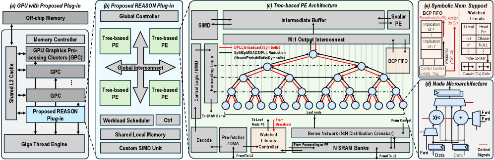
Figure 6: Overview of the REASON hardware acceleration system. (a) Integration of REASON as a GPU co-processor. (b) REASON plug-in architecture with PEs, shared local memory, and global scheduling. (c) Tree-based PE architecture enabling broadcast, reduction, and irregular DAG execution. (d) Micro-architecture of a tree node supporting arithmetic and logical operations. (e) FIFO and memory layout supporting symbolic reasoning.
### IV-B Stage 2: Adaptive DAG Pruning
Motivation. While the unified DAG representation provides a common abstraction, it may contain significant redundancy, such as logically implied literals, inactive substructures, or low-probability paths, that inflate DAG size and degrade performance without improving inference quality.
Methodology. We propose adaptive DAG pruning, a semantics-preserving optimization that identifies and removes redundant paths in symbolic and probabilistic DAGs. For symbolic kernels, pruning targets literals and clauses that are logically redundant. For probabilistic kernels, pruning eliminates low-activation edges that minimally impact inference. This process significantly reduces model size and computational complexity while preserving correctness of logical and probabilistic inference.
#### Pruning of FOL and SAT via implication graph
For SAT solvers and FOL reasoning, we prune redundant literals using implication graphs. Given a CNF formula $\varphi=\bigwedge_{i}\left(\bigvee_{j}l_{ij}\right)$ , each binary clause $(l\lor l^{\prime})$ induces two directed implication edges: $\bar{l}\rightarrow l^{\prime}$ and $\bar{l^{\prime}}\rightarrow l$ . The resulting implication graph captures logical dependencies among literals. We perform a depth-first traversal to compute reachability relationships between literals. If a literal $l^{\prime}$ is always implied by another literal $l$ , then $l^{\prime}$ is a hidden literal. Clauses containing both $l$ and $l^{\prime}$ can safely drop $l^{\prime}$ , reducing clause width without semantic changes. For instance, a clause $C=(l\lor l^{\prime})$ is reduced to $C^{\prime}=(l)$ . This procedure removes redundant literals (e.g., hidden tautologies and failed literals), preserves satisfiability, and runs in time linear in the size of the implication graph.
#### Pruning of PCs and HMMs via circuit flow
For probabilistic DAGs such as PCs and HMMs, we prune edges based on probability flow, which quantifies each edge’s contribution to the overall likelihood.
In HMMs, the DAG is unrolled over time steps, with nodes representing transition factors $p(z_{t}\mid z_{t-1})$ and emission factors $p(x_{t}\mid z_{t})$ . We compute expected transition and emission usage via the forward-backward algorithm, yielding posterior state and transition probabilities. Edges corresponding to transitions or emissions with consistently low posterior probability are pruned, as their contribution to the joint likelihood $p(z_{1:T},x_{1:T})$ is negligible. This pruning preserves inference fidelity while reducing state-transition complexity.
In PCs, sum node $n$ computes $p_{n}(x)=\sum_{c\in\mathrm{ch}(n)}\theta_{n,c}\,p_{c}(x)$ , where $\theta_{n,c}\geq 0$ denotes the weight associated with child $c$ . For an input $x$ , we define the circuit flow through edge $(n,c)$ as $F_{n,c}(x)=\frac{\theta_{n,c}\,p_{c}(x)}{p_{n}(x)}\cdot F_{n}(x)$ , where $F_{n}(x)$ denotes the top-down flow reaching node $n$ . Intuitively, $F_{n,c}(x)$ measures the fraction of probability mass passing through edge $(n,c)$ for input $x$ . Given a dataset $\mathcal{D}$ , the cumulative flow for edge $(n,c)$ is $F_{n,c}(\mathcal{D})=\sum_{x\in\mathcal{D}}F_{n,c}(x)$ . Edges with the smallest cumulative flow are pruned, as they contribute least to the overall model likelihood. The resulting decrease in average log-likelihood is bounded by $\Delta\log\mathcal{L}\leq\frac{1}{|\mathcal{D}|}\sum_{x\in\mathcal{D}}F_{n,c}(x)$ , providing a theoretically grounded criterion for safe pruning.
### IV-C Stage 3: Two-Input DAG Regularization
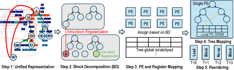
Methodology. After pruning, the resulting DAGs may still have high fan-in or irregular branching, which hinders efficient hardware execution. To address this, we apply a regularization step that transforms DAGs into a canonical two-input form. Specifically, nodes with more than two inputs are recursively decomposed into balanced binary trees composed of two-input intermediate nodes, preserving the original computation semantics. This normalization promotes uniformity, enabling efficient parallel scheduling, pipelining, and mapping onto REASON architecture, without sacrificing model fidelity or expressive power.
For each symbolic or probabilistic kernel, the compiler generates an initial DAG, applies adaptive pruning, and then performs two-input regularization to produce a unified balanced representation. These DAGs are constructed offline and used to generate an execution binary that is programmed onto REASON hardware. This unification-pruning-regularization flow decouples algorithmic complexity from runtime execution and enables predictable performance.
## V REASON: Hardware Architecture
REASON features flexible co-processor plug-in architecture (Sec. V-A), reconfigurable symbolic/probabilistic PEs (Sec. V-B), flexible support for symbolic and probabilistic kernels (Sec. V-C - V-D). Sec. V-E presents cycle-by-cycle execution pipeline analysis. Sec. V-F discusses design space exploration and scalability.
### V-A Overall Architecture
Neuro-symbolic workloads exhibit heterogeneous compute and memory patterns with diverse sparsity, diverging from the GEMM-centric design of conventional hardware. Built on the unified DAG representation and optimizations (Fig. IV), REASON is a reconfigurable and flexible architecture designed to efficiently execute the irregular computations of symbolic and probabilistic reasoning stages in neuro-symbolic AI.
Overview. REASON operates as a programmable co-processor tightly integrated with GPU SMs, forming a heterogeneous system architecture. (Fig. 6 (a)). In this system, REASON serves as an efficient and reconfigurable “slow thinking” engine, accelerating symbolic and probabilistic kernels that are poorly suited to GPU execution. As illustrated in Fig. 6 (b), REASON comprises an array of tree-based PE cores that act as the primary computation engines. A global controller and workload scheduler manage the workload mapping. A shared local memory serves as a unified scratchpad for all cores. Communication between cores and shared memory is handled by a high-bandwidth global interconnect.
Tree architecture. Each PE core is organized as a tree-structured compute engine, as shown in Fig. 6 (c). Each tree node integrates a specialized datapath, memory subsystem, and control logic optimized for executing DAG-based symbolic and probabilistic operations.
Reconfigurable tree engine (RTE). At the core of each PE is a Reconfigurable Tree Engine (RTE), whose datapath forms a bidirectional tree of PEs (Fig. 6 (d)). The RTE supports both SAT-style symbolic broadcast patterns and probabilistic aggregation operations. A Benes network interconnect enables N-to-N routing, decoupling SRAM banking from DAG mapping and simplifying compilation of irregular graph structures (Sec. V-C). Forwarding logic routes intermediate and irregular outputs back to SRAM for subsequent batches.
Memory subsystem. To tackle the memory-bound nature of symbolic and probabilistic kernels, the RTE is backed by a set of dual-port, wide-bitline SRAM banks arranged as a banked L1 cache. A memory front-end with a prefetcher and high-throughput DMA engine moves data from shared scratchpad. A control/memory management unit (MMU) block handles address translation across the distributed memory system.
Core control and execution. A scalar PE acts as the core-level controller, fetching and issuing VLIW-like instructions that configure the RTE, memory subsystem, and specialized units. Outputs from the RTE are buffered before being consumed by the scalar PE or the SIMD Unit, which provides support for executing parallelable subset of symbolic solvers.
### V-B Reconfigurable Symbolic/Probabilistic PE
The PE architecture is designed to support a wide range of symbolic and probabilistic computation patterns via a VLIW-driven cycle-reconfigurable datapath. Each PE can switch among three operational modes to efficiently execute heterogeneous kernels mapped from the unified DAG representation.
Probabilistic mode. In probabilistic mode, the node executes irregular DAGs derived from unified probabilistic representations (Sec. V-C). The nodes are programmed by the VLIW instruction stream to perform arithmetic operations, either addition or multiplication, required by the DAG node mapped onto them. This mode supports probabilistic aggregation patterns such as sum-product computation and likelihood propagation, enabling efficient execution of PCs and HMMs.
<details>
<summary>x7.png Details</summary>
### Visual Description
## Diagram: Computation Graph Mapping and Scheduling Process
### Overview
This image illustrates a five-step technical workflow for mapping a complex computation graph (likely a neural network or decision tree) onto a hardware architecture consisting of Processing Elements (PEs). The process flows from left to right, transforming a unified graph representation into a scheduled sequence of operations on specific hardware components.
### Components/Axes
The diagram is organized into five sequential steps, labeled at the bottom:
1. **Step 1: Unified Representation** (Far Left)
2. **Step 2: Block Decomposition (BD)** (Center-Left)
3. **Step 3: PE and Register Mapping** (Center)
4. **Step 4: Tree Mapping** (Top-Right)
5. **Step 5: Reordering** (Bottom-Right)
### Detailed Analysis
#### Step 1: Unified Representation
* **Visual:** A complex, hierarchical graph structure containing nodes labeled A through I.
* **Details:** The graph is interconnected with various lines representing data flow or dependencies.
* **Annotations:** Two prominent, thick red curved arrows originate from the bottom node (A) and point upward to nodes H and I, indicating long-range dependencies or specific data paths within the graph.
#### Step 2: Block Decomposition (BD)
* **Visual:** Two gray-shaded rectangular regions, each containing two tree-like structures.
* **Annotations:**
* **"Intra-block Regularization"**: A red arrow points from the bottom gray box to the top gray box, indicating a transformation or constraint applied between blocks.
* **"Inner-block Regularization"**: A green arrow points to a specific green-shaded node within the bottom gray box, indicating a transformation or constraint applied within a block.
* **Node A**: The bottom-left node is highlighted in red, corresponding to the starting point in Step 1.
#### Step 3: PE and Register Mapping
* **Visual:**
* **Top:** A grid of eight blue squares, each labeled "PE" (Processing Element).
* **Bottom:** A grid labeled "Tree global scratchpad".
* **Text:** "Assign based on BD" is written between the PE grid and the scratchpad, indicating that the decomposition performed in Step 2 dictates how resources are allocated.
#### Step 4: Tree Mapping
* **Visual:** A "Single PE" block containing a tree structure.
* **Components:**
* The tree nodes are connected to a "Local PE SRAM" (Static Random Access Memory) at the bottom.
* **Arrows:** Colored arrows (purple, yellow, gray) indicate data movement between the "Local PE SRAM" and specific nodes within the tree.
#### Step 5: Reordering
* **Visual:** Four vertical bars representing a timeline of operations.
* **Labels:**
* **T=0**: "Load"
* **T=1**: "Block"
* **T=2**: "No-op" (No operation)
* **T=3**: "Block"
### Key Observations
* **Abstraction Flow:** The diagram demonstrates a clear progression from high-level algorithmic representation (Step 1) to low-level hardware scheduling (Step 5).
* **Regularization:** The use of "Intra-block" and "Inner-block" regularization suggests that the process involves optimizing the graph structure to fit hardware constraints (likely memory or compute limitations).
* **Resource Allocation:** Step 3 explicitly links the logical decomposition (BD) to physical hardware resources (PEs and Scratchpad).
* **Temporal Scheduling:** Step 5 introduces a temporal dimension (T=0 to T=3), showing that the mapping process concludes with a specific execution schedule, including idle cycles ("No-op").
### Interpretation
This diagram represents a **compiler or hardware-mapping pipeline** for specialized hardware accelerators (such as those used for AI inference or decision tree evaluation).
1. **Graph Partitioning:** The process begins by taking a large, unified computation graph and breaking it down into smaller, manageable "blocks" (Step 2). The "Regularization" labels suggest that this partitioning is not arbitrary; it is constrained to ensure the blocks fit within the hardware's memory or compute capabilities.
2. **Hardware Mapping:** Once partitioned, the system maps these logical blocks onto physical hardware (PEs and Scratchpad). The "Assign based on BD" text confirms that the hardware configuration is derived directly from the decomposition strategy.
3. **Execution Scheduling:** The final step (Reordering) demonstrates that the mapping is not just spatial (where data goes) but also temporal (when operations occur). The inclusion of a "No-op" cycle at T=2 suggests that the scheduler must account for hardware latency or synchronization requirements, resulting in a precise execution timeline.
In essence, this is a visual representation of how a software-defined computation graph is "compiled" into a hardware-executable instruction stream.
</details>
Figure 7: Compiler-architecture co-design for probabilistic execution. A probabilistic DAG is decomposed, regularized, mapped onto tree-based PEs, and scheduled with pipeline awareness to enable efficient execution of irregular probabilistic kernels in REASON.
Symbolic mode. In symbolic mode, the datapath is repurposed for logical reasoning operations (Sec. V-D). Key hardware components are utilized as follows: (a) The comparator checks logical states for Boolean Constraint Propagation (BCP), identifying literals as TRUE, FALSE, or UNASSIGNED. (b) The adder performs two key functions: address computation by adding the Clause Base Address and Literal Index to locate the next literal in a clause; and clause evaluation by acting as counter to track the number of FALSE literals. This enables fast detection of unit clauses and conflicts, accelerating SAT-style symbolic reasoning.
SpMSpM mode. The tree-structured PE inherently supports the sparse matrix-matrix multiplication (SpMSpM), a computation pattern widely studied in prior works [24, 45]. In this mode, the leaf nodes are configured as multipliers to compute partial products of the input matrix elements, while the internal nodes are configured as adders to perform hierarchical reductions. This execution pattern allows small-scale neural or neural-symbolic models to be efficiently mapped onto the REASON engine, extending its applicability beyond purely symbolic and probabilistic kernels.
### V-C Architectural Support for Probabilistic Reasoning
Probabilistic reasoning kernels are expressed as DAGs composed of arithmetic nodes (sum and product) connected by data-dependent edges. REASON exploits its pipelined, tree-structured datapath to efficiently map these DAGs onto parallel PEs. Key architectural features include: multi-tree PE mapping for arithmetic DAG execution, a banked register file with flexible crossbar interconnect to support irregular memory access, and compiler-assisted pipeline scheduling with automatic register management to reduce control overhead. Fig. 7 illustrates the overall workflow.
Datapath and pipelined execution. The datapath operates in a pipelined fashion, with each layer of nodes serving as pipeline stages. Each pipeline stage receives inputs from a banked register file, which consists of multiple parallel register banks. Each bank operates independently, providing flexible addressing that accommodates the irregular memory access patterns typical in probabilistic workloads (e.g., PCs, HMMs).
Flexible interconnect. To handle the irregularity in probabilistic DAGs, REASON employs an optimized interconnection. An input Benes crossbar connects the register file banks to inputs of PE trees, allowing flexible and conflict-free routing of operands into computation units. Output connections from PE to register banks are structured as one-bank-one-PE to minimize hardware complexity while preserving flexibility, balancing trade-offs between utilization and performance.
<details>
<summary>x8.png Details</summary>
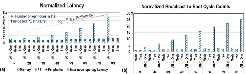
### Visual Description
## Chart/Diagram Type: Comparative Performance Analysis (Normalized Latency and Cycle Counts)
### Overview
This image displays two bar charts, labeled (a) and (b), comparing the performance of three different network topologies ("All-to-One", "Mesh", and "Tree") across varying system sizes (N to 8N).
* **Chart (a)** illustrates "Normalized Latency," highlighting how different components (Memory, PE, Peripheries, Inter-node topology Latency) contribute to total latency.
* **Chart (b)** illustrates "Normalized Broadcast-to-Root Cycle Counts," showing the efficiency of the topologies in broadcast operations.
### Components/Axes
**Shared Legend (Bottom):**
* **Green diagonal stripes:** Memory
* **Orange solid:** PE (Processing Element)
* **Blue dots:** Peripheries
* **Blue diagonal stripes:** Inter-node topology Latency
**Chart (a) - Normalized Latency:**
* **Y-axis:** Normalized Latency, scaled from 0 to 8x.
* **X-axis:** Number of leaf nodes (N, 2N, 3N, 4N, 5N, 6N, 7N, 8N).
* **Sub-categories (per group):** All-to-One, Mesh, Tree.
* **Annotation:** An arrow pointing from N to 8N labeled "Sys. Freq. Bottleneck," indicating an increasing performance constraint for the All-to-One topology.
* **Note:** "N: Number of leaf nodes in the tree-based PE structure."
**Chart (b) - Normalized Broadcast-to-Root Cycle Counts:**
* **Y-axis:** Normalized Broadcast-to-Root Cycle Counts, scaled from 0 to 30x.
* **X-axis:** Number of leaf nodes (N, 2N, 3N, 4N, 5N, 6N, 7N, 8N).
* **Sub-categories (per group):** Mesh, Tree, All-to-One.
---
### Detailed Analysis
#### Chart (a): Normalized Latency
* **Trend:** The "All-to-One" topology shows a dramatic, near-linear increase in "Inter-node topology Latency" as the number of nodes increases from N to 8N. Conversely, "Mesh" and "Tree" topologies maintain a consistently low, flat latency profile across all node counts.
* **Data Points (Approximate):**
* **N:** All-to-One (~1.1x), Mesh (~0.9x), Tree (~0.9x).
* **4N:** All-to-One (~3.0x), Mesh (~0.9x), Tree (~0.9x).
* **8N:** All-to-One (~6.8x), Mesh (~0.9x), Tree (~0.9x).
* **Composition:** In the "All-to-One" bars, the "Inter-node topology Latency" (blue diagonal stripes) constitutes the vast majority of the bar height as N increases, dwarfing the constant "Memory," "PE," and "Peripheries" components.
#### Chart (b): Normalized Broadcast-to-Root Cycle Counts
* **Trend:** The "All-to-One" topology exhibits a steep, upward trend in cycle counts as the system scales. "Mesh" and "Tree" topologies remain extremely efficient, showing very low, nearly flat cycle counts regardless of the number of nodes.
* **Data Points (Approximate):**
* **N:** Mesh (~1x), Tree (~1x), All-to-One (~3x).
* **4N:** Mesh (~2x), Tree (~2x), All-to-One (~12.5x).
* **8N:** Mesh (~2.5x), Tree (~2.5x), All-to-One (~25x).
---
### Key Observations
1. **Scalability Gap:** There is a massive performance disparity between the "All-to-One" topology and the "Mesh/Tree" topologies. As the system scales to 8N, "All-to-One" becomes significantly less efficient.
2. **Bottleneck Identification:** In chart (a), the "Sys. Freq. Bottleneck" annotation explicitly identifies that the "All-to-One" structure suffers from a system frequency bottleneck, which manifests as increased inter-node latency.
3. **Consistency:** The "Mesh" and "Tree" topologies demonstrate excellent scalability, with performance metrics remaining relatively stable even as the number of nodes increases eightfold.
### Interpretation
The data demonstrates that the "All-to-One" communication pattern is fundamentally unscalable for larger systems. The linear growth in both latency and cycle counts suggests that the "All-to-One" approach creates a serialization point or contention at the root node, which becomes increasingly severe as more leaf nodes are added.
The "Mesh" and "Tree" topologies, by contrast, likely utilize distributed communication paths that avoid this bottleneck, allowing them to maintain constant performance. The "Sys. Freq. Bottleneck" annotation in chart (a) implies that the latency penalty in "All-to-One" is not merely a software overhead but is tied to the physical or architectural limits of the interconnect frequency when handling the increased traffic volume of an All-to-One pattern. This suggests that for any system design requiring scalability beyond N, "All-to-One" should be avoided in favor of "Mesh" or "Tree" structures.
</details>
Figure 8: Scalability analysis of interconnect topologies. (a) Normalized latency breakdown as the number of leaf nodes $N$ increases. (b) Normalized broadcast-to-root cycle counts for different PE interconnect structures.
Register management. REASON adopts an automatic write-address generation policy. Data is written to the lowest available register address in each bank, eliminating the need to encode explicit write addresses in instructions. The compiler precisely predicts these write addresses at compile time due to the deterministic execution sequence, further reducing instruction size and energy overhead.
Compiler-driven optimization. To efficiently translate unified DAGs into executable kernels and map onto hardware datapath, REASON adopts a four-step compiler pipeline (Fig. 7).
Step- 1 Block decomposition: The compiler decomposes the unified DAG from Sec. IV into execution blocks through a greedy search that identifies schedulable subgraphs whose maximum depth does not exceed the hardware tree depth. This process maximizes PE utilization while minimizing inter-block dependencies that may cause read-after-write stalls. The resulting tree-like blocks form the basis for efficient mapping.
Step- 2 PE mapping: For each block, the compiler jointly assigns nodes to PEs and operands to register banks, considering topological constraints and datapath connectivity. Nodes are mapped to preserve order, while operands are allocated to banks to avoid simultaneous conflicts. The compiler dynamically updates feasible mappings and prioritizes nodes with the fewest valid options. This conflict-aware strategy minimizes bank contention and balances data traffic across banks.
Step- 3 Tree mapping: Once block and register mappings are fixed, the compiler constructs physical compute trees that maximize data reuse in the REASON datapath. Node fusion and selective replication enhance operand locality and reduce inter-block communication, allowing intermediate results to be consumed within the datapath and lowering memory traffic.
Step- 4 Reordering: The compiler then schedules instructions with awareness of the multi-stage pipeline. Dependent operations are spaced by at least one full pipeline interval, while independent ones are interleaved. Lightweight load, store, and copy operations fill idle cycles without disturbing dependencies. Live-range analysis identifies register pressure and inserts minimal spill and reload instructions when needed.
The DAG-to-hardware mapping is an automated heuristic process to generate a compact VLIW program for REASON. Designers can interact for design-space exploration to tune architectural parameters within flexible hardware template.
### V-D Architectural Support for Symbolic Logical Reasoning
To efficiently support symbolic logical reasoning kernels, REASON features a linked-list-based memory layout and hardware-managed BCP FIFO mechanism (Fig. 6 (e)), enabling efficient and scalable support to large-scale solver kernels that are fundamental to logical reasoning.
Watched literals (WLs) unit. The WLs unit acts as a distributed memory controller tightly integrated with $N$ SRAM banks, implementing the two-watched-literals indexing scheme in hardware. This design transforms the primary bottleneck in BCP from a sequential scan over the clause database into a selective parallel memory access problem. Crucially, it enables scalability to industrial-scale SAT problems [44], where only a small subset of clauses (those on the watch list) need to be accessed at any time. This design naturally aligns with a hierarchical memory system, allowing most clauses to reside in remote scratchpad memory or DRAM, with on-chip SRAM caching only the required clauses indexed by WLs unit.
<details>
<summary>x9.png Details</summary>
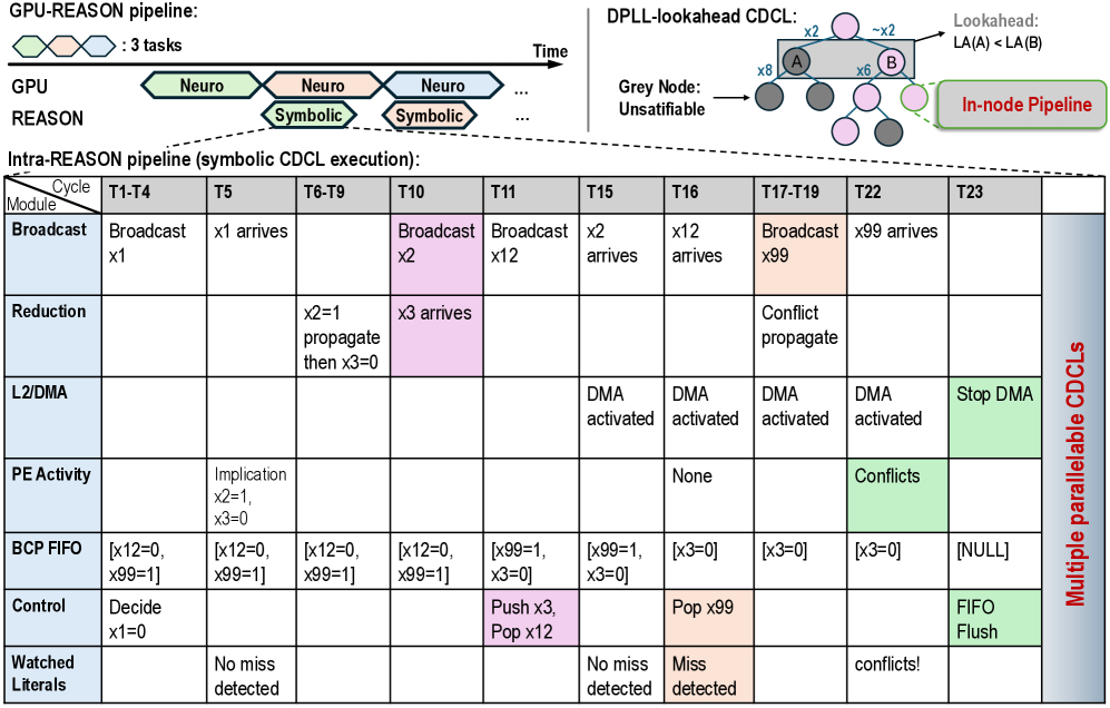
### Visual Description
## Mixed Diagram: GPU-REASON Pipeline and Intra-REASON Execution
### Overview
This image illustrates a hybrid computing architecture designed for symbolic CDCL (Conflict-Driven Clause Learning) execution. It is composed of three distinct sections:
1. **Top-Left:** A timeline diagram showing the concurrent execution of "Neuro" (GPU) and "Symbolic" (REASON) tasks.
2. **Top-Right:** A tree diagram representing the DPLL-lookahead CDCL process, highlighting node exploration and "In-node Pipeline" capabilities.
3. **Bottom:** A detailed execution table ("Intra-REASON pipeline") mapping specific module operations across time cycles (T1–T23).
---
### Components/Axes
#### 1. GPU-REASON Pipeline (Top-Left)
* **Legend:** Three overlapping hexagons (Green, Pink, Blue) labeled ": 3 tasks".
* **Axes:** Horizontal axis represents "Time".
* **Rows:**
* **GPU:** Shows "Neuro" tasks (Green, Pink, Green) occurring in a staggered, overlapping fashion.
* **REASON:** Shows "Symbolic" tasks (Pink, Pink) occurring in the gaps between GPU tasks.
#### 2. DPLL-lookahead CDCL (Top-Right)
* **Structure:** A tree diagram with nodes labeled "A" and "B".
* **Annotations:**
* "Lookahead: LA(A) < LA(B)" pointing to the branch between A and B.
* "Grey Node: Unsatisfiable" pointing to dark grey circles.
* "In-node Pipeline" pointing to a dashed bubble enclosing a light pink node.
#### 3. Intra-REASON Pipeline (Bottom Table)
* **Structure:** A matrix where rows represent functional modules and columns represent time cycles.
* **Modules (Rows):** Broadcast, Reduction, L2/DMA, PE Activity, BCP FIFO, Control, Watched Literals.
* **Time Cycles (Columns):** T1-T4, T5, T6-T9, T10, T11, T15, T16, T17-T19, T22, T23.
* **Right-side Label:** "Multiple parallelable CDCLs" (vertical text).
---
### Content Details: Intra-REASON Pipeline Table
| Module | T1-T4 | T5 | T6-T9 | T10 | T11 | T15 | T16 | T17-T19 | T22 | T23 |
| :--- | :--- | :--- | :--- | :--- | :--- | :--- | :--- | :--- | :--- | :--- |
| **Broadcast** | Broadcast x1 | x1 arrives | | Broadcast x2 (Pink) | Broadcast x12 | x2 arrives | x12 arrives | Broadcast x99 (Orange) | x99 arrives | |
| **Reduction** | | | x2=1 propagate then x3=0 | x3 arrives (Pink) | | | | Conflict propagate | | |
| **L2/DMA** | | | | | | DMA activated | DMA activated | DMA activated | DMA activated | Stop DMA (Green) |
| **PE Activity** | | Implication x2=1, x3=0 | | | | | None | | Conflicts (Green) | |
| **BCP FIFO** | [x12=0, x99=1] | [x12=0, x99=1] | [x12=0, x99=1] | [x12=0, x99=1] | [x99=1, x3=0] | [x99=1, x3=0] | [x3=0] | [x3=0] | [x3=0] | [NULL] |
| **Control** | Decide x1=0 | | | | Push x3, Pop x12 (Pink) | | Pop x99 (Orange) | | | FIFO Flush (Green) |
| **Watched Literals** | | No miss detected | | | | No miss detected | Miss detected (Orange) | | conflicts! | |
---
### Key Observations
* **Color Coding:**
* **Pink:** Indicates active control/broadcast operations (e.g., T10 Broadcast x2, T11 Push/Pop).
* **Orange:** Indicates conflict/miss events (e.g., T16 Miss detected, T17-T19 Broadcast x99).
* **Green:** Indicates termination or conflict states (e.g., T22 Conflicts, T23 Stop DMA/FIFO Flush).
* **Data Flow:** The BCP FIFO (Boolean Constraint Propagation First-In-First-Out) buffer maintains state across cycles, with values like `x99=1` and `x3=0` persisting until they are popped or updated.
* **Parallelism:** The "Multiple parallelable CDCLs" label on the right suggests that the table represents a single slice of a larger, parallelized execution architecture.
* **Temporal Gaps:** There are gaps in the timeline (e.g., between T11 and T15, T19 and T22) suggesting asynchronous processing or idle cycles where no specific module activity is recorded.
---
### Interpretation
This diagram describes a hardware-accelerated solver architecture. The **GPU-REASON pipeline** (top-left) demonstrates a heterogeneous computing model where the GPU handles "Neuro" (likely neural network-based heuristics or predictions) and the REASON unit handles "Symbolic" (logical deduction/CDCL) tasks.
The **Intra-REASON pipeline** table provides a low-level trace of the symbolic solver's state machine.
* **The Logic:** The solver is performing clause learning. It broadcasts literals (x1, x2, x12, x99), propagates implications (x2=1, x3=0), and manages a FIFO queue of literals.
* **Conflict Handling:** The system is designed to detect "Misses" (Watched Literals) and "Conflicts" (PE Activity). When a conflict occurs (T17-T19, T22), the system triggers a propagation and eventually flushes the FIFO (T23), indicating a reset or backtracking step common in CDCL algorithms.
* **Efficiency:** The "In-node Pipeline" (top-right) and the table suggest that the architecture is optimized to perform these logical operations in hardware, allowing for "Lookahead" capabilities where the system can evaluate branches (A vs B) before fully committing to them, thereby pruning the search space more efficiently than a standard CPU-based solver.
</details>
Figure 9: Two-level execution pipeline for symbolic reasoning. Top: task-level overlap between GPU neural execution and REASON symbolic execution. Bottom: detailed cycle-by-cycle timeline of CDCL SAT solving, illustrating pipelined broadcast/reduction, WLs traversal, latency hiding, and priority-based conflict handling. Color represents the causality of hardware events.
SRAM layout. The local SRAM is partitioned to support a linked-list-based organization of watch lists. A dedicated region stores a head pointer table indexed by literal IDs, each pointing to the start of a watch list, enabling $\mathcal{O}(1)$ access. The main data region stores clauses, each augmented with a next-watch pointer that links to other clauses watching the same literal, forming multiple linked lists within the linear address space. Upon a variable assignment, the WLs unit uses the literal ID to fetch the head pointer and traverses the list by following next-watch pointers, dispatching only the relevant clause to PEs. This hardware-managed indexing eliminates full-database scans and maps efficiently to the adder datapath.
BCP FIFO. The BCP FIFO sits atop the M:1 output interconnect (Fig. 6 (c)) and serializes multiple parallel implications generated by the leaf tree-node in a single cycle. While many implications can be discovered concurrently, BCP must propagate them sequentially to preserve the causality chain for conflict analysis. The controller immediately broadcasts one implication back into the pipeline, while the rest are queued in the FIFO and processed in a pipelined manner. Within a symbolic (DPLL) tree node, implications are causally independent and can be pipelined, but between assignments, sequential ordering is enforced to maintain correctness. Sec. V-E illustrates a detailed cycle-level execution example.
Scalability advantages. A key advantage of the REASON architecture is that its tree-based inter-node topology does not become a bottleneck as the symbolic DPLL tree grows (Fig. 8 (a)). In contrast, all-to-one (or one-to-all) bus interconnects often fail to scale due to post-layout electrical constraints, including high fan-out and buffer insertion for hold-time fixes. Moreover, given that broadcasting is a dominant operation, the root-to-leaf traversal latency is critical. REASON’s tree-based inter-node topology achieves exceptional scalability with an $\mathcal{O}(\log N)$ traversal latency, compared to $\mathcal{O}(\sqrt{N})$ for mesh-based designs and $\mathcal{O}(N)$ for bus-based interconnects (Fig. 8 (b)). This property enables robust scalability for large symbolic reasoning workloads.
Listing 1: C++ Programming Interface of REASON
⬇
// Trigger symbolic execution for a single inference
void REASON_execute (
int batch_id, // batch identifier
int batch_size, // number of objects in the batch
const void * neural_buffer, // neural results in shared memory
const void * reasoning_mode, // mode selection
void * symbolic_buffer // write-back symb. results
);
// Query current REASON status for a given object
int REASON_check_status (
int batch_id, // batch identifier
bool blocking // wait till REASON is idle
);
### V-E Case Study: A Working Example of Symbolic Execution
Fig. 9 illustrates the dynamic, pipelined per-node execution of REASON during a cube-and-conquer SAT solving phase, which highlights several key hardware mechanisms, including inter-node pipelined broadcast/reduction, latency hiding via parallel WLs traversal, and priority-based conflict handling.
Execution begins with the controller issuing a Decision to assign $x_{1}$ , which is broadcast through the distribution tree (T1–T4). At T5, leaf nodes concurrently discover two implications: $x_{2}$ = $1$ and $x_{3}$ = $0$ . These implications are returned to the controller via the reduction tree in a pipelined manner, where $x_{2}$ = $1$ arrives first, followed by $x_{3}$ = $0$ at T10. Since the FIFO is occupied, $x_{3}$ = $0$ is queued into the BCP FIFO at T11.
At T15, the FIFO pops a subsequent implication ( $x_{12}$ ), which triggers WLs lookup. A local SRAM miss prompts the L2/DMA to begin fetching clause, meanwhile BCP FIFO continues servicing queued implications: $x_{99}$ is popped and broadcast from T17–T19 while DMA fetch is still in progress.
At T22, the propagation of $x_{99}$ results in a Conflict, which immediately propagates up the reduction tree. Upon receiving the conflict signal at T23, the controller asserts priority control: it halts the ongoing DMA fetch, flushes the FIFO, and discards all pending implications (including $x_{3}$ = $0$ ) from the now-invalid search path. The cube-and-conquer phase terminates, and the parallelized DPLL node is forwarded to the scalar PE for CDCL conflict analysis, as discussed in Sec. II-C.
### V-F Design Space Exploration and Scalability
Design space exploration. To identify the optimal configuration of REASON architecture, we perform a comprehensive design space exploration. We systematically evaluated different configurations by varying key architectural parameters such as the depth of the tree (D), the number of parallel register banks (B), and the number of registers per bank (R). We evaluate each configuration across latency, energy consumption, and energy-delay product (EDP) on representative workloads. The selected configuration (D=3, B=64, R=32) offers the optimal trade-off between performance and energy efficiency.
Scalability and variability support. Coupled with reconfigurable array, pipeling scheduling, and memory layout optimizations, REASON provides flexible hardware support across symbolic and probabilistic kernels (e.g., SAT, FOL, PC, HMM), neuro-symbolic workloads, and cognitive tasks, enabling efficient neuro-symbolic processing at scale (Sec. VII).
Design choice discussion. We adopt a unified architecture for symbolic and probabilistic reasoning to maximize flexibility and efficiency, rather than decoupling them into separate engines. We identify these kernels share common DAG patterns, enabling REASON to execute them on Tree-PEs through a unified representation. This approach achieves $>$ 90% utilization with 58% lower area/power than decoupled designs, while maintaining tight symbolic-probabilistic coupling. A flexible Benes network and compiler co-design handle routing and memory scheduling, ensuring efficient execution.
## VI REASON: System Integration and Pipeline
This section presents the system-level integration of REASON. We first present the integration principles and workload partitioning strategy between GPU and REASON (Sec. VI-A), then introduce the programming model that enables flexible invocation and synchronization (Sec. VI-B). Finally, we describe the two-level execution pipeline (Sec. VI-C).
### VI-A Integration with GPUs for End-to-End Reasoning
Integration principles. As illustrated in Fig. 6 (a), the proposed REASON is integrated as a co-processor within GPU system to support efficient end-to-end symbolic and probabilistic reasoning. This integration follows two principles: (1) Versatility to ensure compatibility with a broad range of logical and probabilistic reasoning workloads in neuro-symbolic pipelines, and (2) Efficiency to achieve low-latency execution for real-time reasoning. These principles necessitate careful workload assignment between GPU and REASON with pipelined execution.
Workload partitioning. To maximize performance while preserving compatibility with existing and emerging LLM-based neuro-symbolic agentic pipelines, we assign neural computation (e.g., LLM inference) to the GPU and offload symbolic reasoning and probabilistic inference to REASON. This partitioning exploits the GPU’s high throughput and programmability for neural kernels, while leveraging REASON’s reconfigurable architecture optimized for logical and probabilistic operations. It also minimizes data movement and enables pipelined execution: while REASON processes symbolic reasoning for the current batch, the GPU concurrently executes neural computation for the next batch.
### VI-B Programming Model
REASON’s programming model (Listing. 1) is designed to offer full flexibility and control, making it easy to utilize REASON for accelerating various neuro-symbolic applications. It exposes two core functions for executing and status checking, enabling acceleration of logical and probabilistic kernels.
REASON_execute is responsible for processing a single symbolic reasoning run. It is called after GPU SMs complete processing the neural LLM. REASON then performs logical reasoning and probabilistic inference, and writes the symbolic results to shared memory, where SMs use for the next iteration.
REASON_check_status reports the current execution status of REASON (IDLE or EXECUTION) and includes an optional blocking flag. This feature allows the host thread to wait for REASON to complete the current step of reasoning before starting the next, ensuring proper coordination across subtasks without relying on CUDA stream synchronization.
Synchronization. Coordination between SMs and REASON is handled through shared-memory flag buffers and L2 cache. After executing LLM kernel, SMs write the output to shared memory and set neural_ready flag. REASON polls this flag, fetches the data, and performs symbolic reasoning. It then writes the result back to shared memory and sets symbolic_ready flag, which will be retrieved for final output. This tightly coupled design leverages GPU’s throughput for LLM kernels and REASON’s efficiency for symbolic reasoning, minimizing overhead and maximizing performance.
TABLE III: Hardware baselines. Comparison of device specs.
| Orin NX [18] | 8 nm | 4 MB | 512 CUDA Cores | 450 | 15 |
| --- | --- | --- | --- | --- | --- |
| RTX A6000 [48] | 8 nm | 16.5 MB | 10572 CUDA Cores | 628 | 300 |
| Xeon CPU [17] | 10 nm | 112.5 MB | 60 cores per socket | 1600 | 270 |
| TPU [19] | 7 nm | 170 MB | 8 128 $\times$ 128 PEs | 400 | 192 |
| DPU # [59] | 28 nm | 2.4 MB | 8 PEs / 56 Nodes | 3.20 | 1.10 |
| REASON | 28 nm | 1.25 MB | 12 PEs / 80 Nodes | 6.00 | 2.12 |
| REASON * | 12 nm | 1.25 MB | 12 PEs / 80 Nodes | 1.37 | 1.21 |
| REASON * | 8 nm | 1.25 MB | 12 PEs / 80 Nodes | 0.51 | 0.98 |
- The 12nm and 8nm data are scaled from the DeepScaleTool [57] with a voltage of 0.8V and a frequency of 500MHz. # The terminology for tree-based architecture is renamed from tree to PE and PE to node to align with the proposed REASON.
### VI-C Two-Level Execution Pipeline
Our system-level design employs a two-level pipelined execution model (Fig. 9 top-left) to maximize concurrency across neural and symbolic kernels. The GPU-REASON pipeline overlaps the execution of symbolic kernels on REASON for step $N$ with neural kernels on GPU for step $N$ +1, effectively hiding the latency of one stage and improving throughput. Within REASON, the Intra-REASON pipeline exploits inter-node pipelined broadcast and reduction to hide communication latency, using parallel worklist traversal and priority-based conflict handling to accelerate symbolic kernels (Sec. V-E). The compiler integrates pipeline-aware scheduling to reorder instructions, avoid read-after-write hazards, and insert no-operation instructions when necessary, ensuring each stage receives valid data without interruption.
<details>
<summary>x10.png Details</summary>
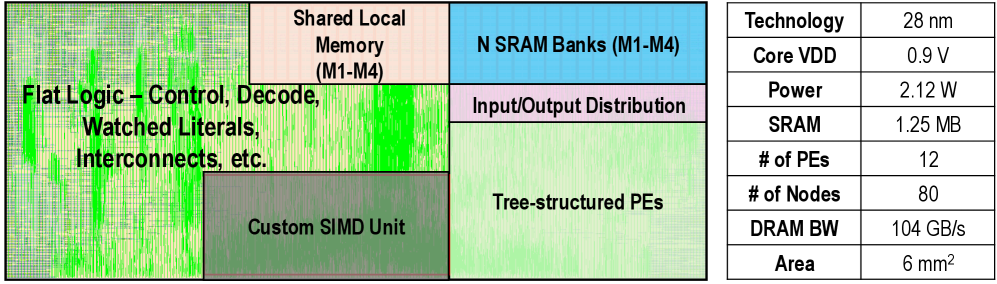
### Visual Description
## Block Diagram and Specification Table: Chip Architecture Overview
### Overview
The image presents a high-level architectural floorplan of a semiconductor chip alongside a corresponding technical specification table. The diagram illustrates the functional partitioning of the chip's silicon area, while the table provides quantitative performance and physical metrics for the design.
### Components/Axes
**Diagram Components (Left Side):**
The diagram is a rectangular block layout representing the chip's functional units:
* **Left Region:** A large, textured green block labeled "Flat Logic – Control, Decode, Watched Literals, Interconnects, etc."
* **Top-Center Region:** A light peach-colored block labeled "Shared Local Memory (M1-M4)."
* **Top-Right Region:** A light blue block labeled "N SRAM Banks (M1-M4)."
* **Middle-Right Region:** A light purple/pink block labeled "Input/Output Distribution."
* **Bottom-Center Region:** A dark grey/brown block labeled "Custom SIMD Unit."
* **Bottom-Right Region:** A light green block labeled "Tree-structured PEs."
**Table Components (Right Side):**
A two-column table listing technical specifications:
* **Column 1 (Parameter):** Technology, Core VDD, Power, SRAM, # of PEs, # of Nodes, DRAM BW, Area.
* **Column 2 (Value):** 28 nm, 0.9 V, 2.12 W, 1.25 MB, 12, 80, 104 GB/s, 6 mm².
### Detailed Analysis
**Table Data Extraction:**
| Parameter | Value |
| :--- | :--- |
| Technology | 28 nm |
| Core VDD | 0.9 V |
| Power | 2.12 W |
| SRAM | 1.25 MB |
| # of PEs | 12 |
| # of Nodes | 80 |
| DRAM BW | 104 GB/s |
| Area | 6 mm² |
**Diagram Layout Analysis:**
* **Control/Logic:** The "Flat Logic" block occupies the largest portion of the chip area, indicating that the control, decoding, and interconnect logic (specifically for "Watched Literals") is the primary consumer of silicon real estate.
* **Memory Hierarchy:** The memory is split into two distinct types: "Shared Local Memory" and "N SRAM Banks," suggesting a tiered memory architecture to support the processing units.
* **Processing Units:** The chip utilizes a heterogeneous processing approach, combining a "Custom SIMD Unit" with "Tree-structured PEs" (Processing Elements).
### Key Observations
* **Specialized Architecture:** The inclusion of "Watched Literals" in the logic block is a highly specific indicator. This terminology is standard in Boolean Satisfiability (SAT) solver algorithms. This suggests the chip is a domain-specific accelerator designed for SAT solving or similar constraint-satisfaction problems.
* **Compact Design:** The total area is 6 mm², which is quite small for a chip containing 12 PEs and 80 nodes, indicating a high-density, efficient design.
* **Power Efficiency:** A power consumption of 2.12 W at 0.9 V is relatively low, consistent with a specialized accelerator rather than a general-purpose processor.
* **Memory Bandwidth:** The DRAM bandwidth of 104 GB/s is significant for a chip of this size, suggesting the architecture is designed to handle high-throughput data movement between the memory and the processing elements.
### Interpretation
The data suggests this is a **domain-specific hardware accelerator** optimized for SAT solving.
* **Why it matters:** General-purpose CPUs are often inefficient at the specific logic required for SAT solving (which involves checking large sets of boolean clauses). By implementing "Watched Literals" directly in the "Flat Logic" and utilizing "Tree-structured PEs," this architecture likely achieves massive parallelism and speedups compared to software-based solvers.
* **Structural Relationships:** The "Flat Logic" acts as the central nervous system, likely managing the state of the SAT clauses. The "Custom SIMD Unit" and "Tree-structured PEs" likely perform the actual evaluation of these clauses in parallel. The memory blocks (SRAM and Shared Local Memory) serve as the high-speed cache for the clause database, minimizing the need to access external DRAM, though the high DRAM bandwidth (104 GB/s) indicates that the chip is prepared to handle large problem instances that exceed on-chip memory capacity.
</details>
Figure 10: REASON layout and specifications. The physical design and key operating specifications of our proposed REASON hardware.
## VII Evaluation
This section introduces REASON evaluation settings (Sec. VII-A), and benchmarks the proposed algorithm optimizations (Sec. VII-B) and hardware architecture (Sec. VII-C).
### VII-A Evaluation Setup
Datasets. We evaluate REASON on 10 commonly-used reasoning datasets: IMO [66], MiniF2F [86], TwinSafety [20], XSTest [56], CommonGen [31], News [85], CoAuthor [26], AwA2 [78], FOLIO [11], and ProofWriter [65]. The tasks are measured by the reasoning and deductive accuracy.
Algorithm setup. We evaluate REASON on six state-of-the-art neuro-symbolic models, i.e., AlphaGeometry [66], R 2 -Guard [20], GeLaTo [82], Ctrl-G [83], NeuroPC [6], and LINC [52]. Following the setup in the original literature, we determine the hyperparameters based on end-to-end reasoning performance on the datasets. Our proposed REASON algorithm optimizations are general and can work as a plug-and-play extension to existing neuro-symbolic algorithms.
Baselines. We consider several hardware baselines, including Orin NX [18] (since our goal is to enable real-time neuro-symbolic at edge), RTX GPU [48], Xeon CPU [17], ML accelerators (TPU [19], DPU [59]). Tab. III lists configurations.
Hardware setup. We implement REASON architecture with [59] as the baseline template, synthesize with Synopsys DC [63], and place and route using Cadence Innovus [5] at TSMC 28nm node. Fig. 10 illustrates the layout and key specifications. The REASON hardware consumes an area of 6 mm 2 and an average power of 2.12 W across workloads based on Synopsys PTPX [64] power-trace analysis (Fig. 12 (a)). Unlike conventional tree-based arrays that mainly target neural workloads, REASON provides unified, reconfigurable support for neural, symbolic, and probabilistic computation.
Simulation setup. To evaluate end-to-end performance of REASON when integrated with GPUs, we develop a cycle-accurate simulator based on Accel-Sim (built on GPGPU-Sim) [21]. The simulator is configured for Orin NX architecture. The on-chip GPU is modeled with 8 SMs, each supporting 32 threads per warp, 48 KB shared memory, and 128 KB L1 cache, with a unified 2 MB L2 cache shared across SMs. The off-chip memory uses a 128-bit LPDDR5 interface with 104 GB/s peak BW. DRAM latency and energy are modeled using LPDDR5 timing parameters.
Simulator test trace derivation. We use GPGPU-Sim to model interactions between SMs and REASON, including transferring neural results from SMs to REASON and returning symbolic reasoning results from REASON to SMs. To simulate communication overhead, we extract memory access traces from neuro-symbolic model execution on Orin, capturing data volume and access patterns as inputs to GPGPU-Sim for accurate modeling. For GPU comparison baselines, we use real hardware measurements to get accurate ground-truth data.
### VII-B REASON Algorithm Performance
TABLE IV: REASON algorithm optimization performance. REASON achieves comparable accuracy with reduced memory footprint via unified DAG representation, adaptive pruning, and regularization.
| Workloads | Benchmarks | Metrics | Baseline Performance | After REASON Algo. Opt. | |
| --- | --- | --- | --- | --- | --- |
| Performance | Memory $\downarrow$ | | | | |
| AlphaGeo | IMO | Accuracy ( $\uparrow$ ) | 83% | 83% | 25% |
| MiniF2F | Accuracy ( $\uparrow$ ) | 81% | 81% | 21% | |
| R 2 -Guard | TwinSafety | AUPRC ( $\uparrow$ ) | 0.758 | 0.752 | 37% |
| XSTest | AUPRC ( $\uparrow$ ) | 0.878 | 0.881 | 30% | |
| GeLaTo | CommonGen | BLEU ( $\uparrow$ ) | 30.3 | 30.2 | 41% |
| News | BLEU ( $\uparrow$ ) | 5.4 | 5.4 | 27% | |
| Ctrl-G | CoAuthor | Success rate ( $\uparrow$ ) | 87% | 86% | 29% |
| NeuroSP | AwA2 | Accuracy | 87% | 87% | 43% |
| LINC | FOLIO | Accuracy ( $\uparrow$ ) | 92% | 91% | 38% |
| ProofWriter | Accuracy ( $\uparrow$ ) | 84% | 84% | 26% | |
Reasoning accuracy. To evaluate REASON algorithm optimization (Sec. IV), we benchmark it on ten reasoning tasks (Sec. VII-A). Tab. IV lists the arithmetic performance and DAG size reduction. We observe that REASON achieves comparable reasoning accuracy through unification and adaptive DAG pruning. Through pruning and regularization, REASON enables 31.7% memory footprint savings on average of ten reasoning tasks across six neuro-symbolic workloads.
### VII-C REASON Architecture Performance
Performance improvement. We benchmark REASON accelerator with Orin NX, RTX GPU, and Xeon CPU for accelerating neuro-symbolic algorithms on 10 reasoning tasks (Fig. 11). For GPU baseline, for neuro kernels, we use Pytorch package that leverages CUDA and cuBLAS/cuDNN libraries; for symbolic kernels, we implement custom kernels optimized for logic and probabilistic operations. The workload is tiled by CuDNN in Pytorch based on block sizes that fit well in GPU memory. We observe that REASON exhibits consistent speedup across datasets, e.g., 50.65 $\times$ /11.98 $\times$ speedup over Orin NX and RTX GPU. Furthermore, REASON achieves real-time performance ( $<$ 1.0 s) on solving math and cognitive reasoning tasks, indicating that REASON enables real-time probabilistic logical reasoning-based neuro-symbolic system with superior reasoning and generalization capability, offering a promising solution for future cognitive applications.
<details>
<summary>x11.png Details</summary>
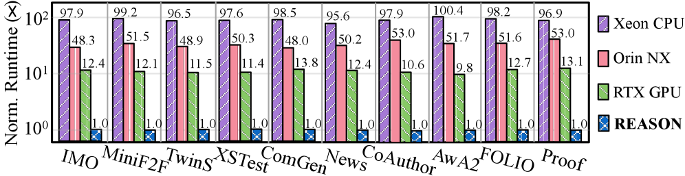
### Visual Description
## Bar Chart: Normalized Runtime Comparison across Hardware/Software Configurations
### Overview
This image displays a grouped bar chart comparing the "Norm. Runtime" (Normalized Runtime) of four different systems—Xeon CPU, Orin NX, RTX GPU, and REASON—across ten distinct tasks or datasets (IMO, MiniF2F, TwinS, XSTest, ComGen, News, CoAuthor, AwA2, FOLIO, Proof). The Y-axis uses a logarithmic scale, highlighting significant performance differences between the configurations.
### Components/Axes
* **Y-Axis:** Labeled "Norm. Runtime". The scale is logarithmic, ranging from $10^0$ (1) to $10^2$ (100).
* **X-Axis:** Lists ten categories: IMO, MiniF2F, TwinS, XSTest, ComGen, News, CoAuthor, AwA2, FOLIO, Proof.
* **Legend (Right side):**
* **Purple (hatched):** Xeon CPU
* **Pink (solid):** Orin NX
* **Green (hatched):** RTX GPU
* **Blue (hatched):** REASON
### Detailed Analysis
The chart presents a consistent hierarchy of performance across all ten categories. REASON is consistently the fastest (normalized to 1.0), followed by the RTX GPU, then the Orin NX, with the Xeon CPU consistently showing the highest runtime.
Below is the data extracted for each category:
| Category | Xeon CPU (Purple) | Orin NX (Pink) | RTX GPU (Green) | REASON (Blue) |
| :--- | :--- | :--- | :--- | :--- |
| **IMO** | 97.9 | 48.3 | 12.4 | 1.0 |
| **MiniF2F** | 99.2 | 51.5 | 12.1 | 1.0 |
| **TwinS** | 96.5 | 48.9 | 11.5 | 1.0 |
| **XSTest** | 97.6 | 50.3 | 11.4 | 1.0 |
| **ComGen** | 98.5 | 48.0 | 13.8 | 1.0 |
| **News** | 95.6 | 50.2 | 12.4 | 1.0 |
| **CoAuthor** | 97.9 | 53.0 | 10.6 | 1.0 |
| **AwA2** | 100.4 | 51.7 | 9.8 | 1.0 |
| **FOLIO** | 98.2 | 51.6 | 12.7 | 1.0 |
| **Proof** | 96.9 | 53.0 | 13.1 | 1.0 |
### Key Observations
* **Performance Hierarchy:** The performance order is invariant across all tasks: REASON (fastest) > RTX GPU > Orin NX > Xeon CPU (slowest).
* **Magnitude of Difference:** Because the Y-axis is logarithmic, the visual gaps represent orders of magnitude. REASON is approximately 10x faster than the RTX GPU, ~50x faster than the Orin NX, and ~100x faster than the Xeon CPU.
* **Consistency:** The runtime values for each hardware configuration remain relatively stable across all tasks, suggesting that the performance characteristics of these systems are not highly dependent on the specific dataset/task type provided.
* **Outliers:**
* **AwA2** shows the highest runtime for the Xeon CPU (100.4) and the lowest runtime for the RTX GPU (9.8).
* **CoAuthor** and **Proof** share the highest runtime for the Orin NX (53.0).
### Interpretation
The data demonstrates that "REASON" is a highly optimized inference engine or framework, providing a massive performance advantage (normalized to 1.0) compared to standard hardware execution environments.
The use of a logarithmic scale is critical here; without it, the REASON bars (at 1.0) would be invisible compared to the Xeon CPU bars (near 100). This visualization is likely intended to showcase the efficiency gains of the REASON system. The fact that the relative performance remains consistent across diverse tasks (ranging from mathematical proofs like IMO/MiniF2F to text generation like CoAuthor/News) suggests that REASON provides a generalized speedup rather than one specific to a single type of workload.
</details>
Figure 11: End-to-end runtime improvement. REASON consistently outperforms Xeon CPU, Orin NX, and RTX GPU in end-to-end runtime latency evaluated on 10 logical and cognitive reasoning tasks.
<details>
<summary>x12.png Details</summary>
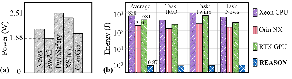
### Visual Description
This document provides a detailed technical extraction and analysis of the provided image, which contains two distinct charts labeled (a) and (b).
## Charts: Power and Energy Consumption Analysis
### Overview
The image displays two side-by-side charts comparing performance metrics across different tasks and hardware configurations.
* **Chart (a)** is a bar chart illustrating the **Power (W)** consumption for five specific tasks/datasets.
* **Chart (b)** is a grouped bar chart illustrating the **Energy (J)** consumption on a logarithmic scale for four categories (Average and three specific tasks) across four hardware/software configurations.
---
### Components/Axes
#### Chart (a) - Left
* **Y-Axis:** Power (W). The scale is linear, starting at 0. There are two horizontal dashed reference lines at 1.88 W and 2.51 W.
* **X-Axis:** Categorical labels: "News", "AwA2", "TwinSafety", "XSTest", "ComGen".
* **Data Series:** Single series of grey bars with diagonal hatching.
#### Chart (b) - Right
* **Y-Axis:** Energy (J). The scale is logarithmic, ranging from $10^0$ to $10^3$.
* **X-Axis:** Categorical groups: "Average", "Task: IMO", "Task: TwinS", "Task: News".
* **Legend (Far Right):**
* **Purple (Diagonal Hatch):** Xeon CPU
* **Pink (Vertical Lines):** Orin NX
* **Green (Diagonal Hatch):** RTX GPU
* **Blue (Grid/Cross-hatch):** REASON
* **Data Series:** Four grouped bars per category, corresponding to the legend above.
---
### Detailed Analysis
#### Chart (a): Power (W)
The bars represent the power draw for specific tasks.
* **News:** Approximately 2.0 W.
* **AwA2:** Exactly 1.88 W (aligns with the lower dashed reference line).
* **TwinSafety:** Exactly 2.51 W (aligns with the upper dashed reference line).
* **XSTest:** Approximately 2.4 W (slightly below the 2.51 W line).
* **ComGen:** Approximately 1.95 W (slightly above the 1.88 W line).
#### Chart (b): Energy (J)
This chart uses a logarithmic scale. The values are estimated based on the visual position relative to the grid lines ($10^0=1, 10^1=10, 10^2=100, 10^3=1000$).
| Category | Xeon CPU (Purple) | Orin NX (Pink) | RTX GPU (Green) | REASON (Blue) |
| :--- | :--- | :--- | :--- | :--- |
| **Average** | ~838 J | ~310 J | ~681 J | ~0.87 J |
| **Task: IMO** | ~500 J | ~180 J | ~300 J | ~1.0 J |
| **Task: TwinS** | ~1200 J | ~350 J | ~900 J | ~1.0 J |
| **Task: News** | ~750 J | ~220 J | ~400 J | ~1.0 J |
*Note: The "REASON" bars are consistently very low, hovering near the $10^0$ (1 Joule) mark, whereas the hardware components (Xeon, Orin, RTX) operate in the $10^2$ to $10^3$ Joule range.*
---
### Key Observations
1. **Hardware Hierarchy:** In Chart (b), the Xeon CPU consistently consumes the most energy across all tasks, followed by the RTX GPU, and then the Orin NX.
2. **Efficiency Gap:** There is a massive disparity between the hardware components and "REASON." While the hardware components consume energy in the hundreds of Joules, "REASON" consumes energy at or below 1 Joule. This represents an efficiency improvement of roughly 2 to 3 orders of magnitude.
3. **Task Intensity:** "Task: TwinS" is the most energy-intensive task across all hardware platforms (Xeon, Orin, RTX), while "Task: IMO" appears to be the least energy-intensive.
---
### Interpretation
The data demonstrates a significant optimization or efficiency advantage provided by "REASON" compared to standard hardware implementations (Xeon CPU, Orin NX, RTX GPU).
* **Reading between the lines:** The logarithmic scale in Chart (b) is necessary because the energy consumption of the hardware components is so vastly higher than that of "REASON" that they would not be comparable on a linear scale.
* **Peircean Investigative View:** The juxtaposition of Power (W) in chart (a) and Energy (J) in chart (b) suggests that while the power draw of the tasks is relatively constrained (between ~1.8W and ~2.5W), the *total energy* required to complete these tasks varies wildly depending on the underlying architecture. The "REASON" component likely represents a highly optimized software or algorithmic approach that completes the tasks significantly faster or with far less computational overhead than the hardware-bound processes, resulting in the drastic reduction in total energy (Joules = Watts × Time).
</details>
Figure 12: Energy efficiency improvement. (a) Power analysis of REASON across workloads. (b) Energy efficiency comparison between REASON and CPUs/GPUs, evaluated from 10 reasoning tasks.
<details>
<summary>x13.png Details</summary>

### Visual Description
## Bar Chart: Normalized Runtime Comparison of Architectures
### Overview
This image presents a grouped bar chart comparing the normalized runtime of three distinct hardware architectures—**TPU-like (systolic-based array)**, **DPU-like (tree-based array)**, and **REASON**—across three workload categories: "Neuro-Only," "Symbolic-Only (logical/probabilistic)," and "End-to-End Neuro+Symbolic." The Y-axis uses a logarithmic scale to accommodate the wide variance in performance data.
### Components/Axes
* **Y-Axis:** "Norm. Runtime (x)". This is a logarithmic scale ranging from $10^0$ (1) to $10^2$ (100).
* **X-Axis:** Divided into three major panels:
1. **Neuro-Only**
2. **Symbolic-Only (logical/probabilistic)**
3. **End-to-End Neuro+Symbolic**
* Within each panel, there are six sub-categories: **AlphaG, Guard, GeLaTo, Ctrl-G, NPC, LINC**.
* **Legend (Positioned at the top-left):**
* **Green (diagonal stripes):** TPU-like (systolic-based array)
* **Pink (solid):** DPU-like (tree-based array)
* **Blue (cross-hatch):** REASON
### Detailed Analysis
The data is normalized to the **REASON** architecture, which is consistently set to a value of **1.00** across all categories.
#### 1. Neuro-Only
* **Trend:** TPU-like architectures consistently outperform REASON (values < 1.0), while DPU-like architectures are consistently slower (values > 4.0).
* **Values:**
* **AlphaG:** TPU (0.69), DPU (4.31), REASON (1.00)
* **Guard:** TPU (0.71), DPU (4.40), REASON (1.00)
* **GeLaTo:** TPU (0.68), DPU (4.29), REASON (1.00)
* **Ctrl-G:** TPU (0.66), DPU (4.49), REASON (1.00)
* **NPC:** TPU (0.73), DPU (4.32), REASON (1.00)
* **LINC:** TPU (0.68), DPU (4.30), REASON (1.00)
#### 2. Symbolic-Only (logical/probabilistic)
* **Trend:** Both TPU-like and DPU-like architectures are significantly slower than REASON. TPU-like architectures show the highest runtime (poorest performance), ranging from ~75x to ~109x. DPU-like architectures perform better than TPU-like but are still significantly slower than REASON.
* **Values:**
* **AlphaG:** TPU (81.35), DPU (25.13), REASON (1.00)
* **Guard:** TPU (76.10), DPU (4.84), REASON (1.00)
* **GeLaTo:** TPU (109.24), DPU (5.03), REASON (1.00)
* **Ctrl-G:** TPU (78.48), DPU (6.07), REASON (1.00)
* **NPC:** TPU (74.71), DPU (4.97), REASON (1.00)
* **LINC:** TPU (90.89), DPU (23.97), REASON (1.00)
#### 3. End-to-End Neuro+Symbolic
* **Trend:** All architectures are slower than REASON. TPU-like architectures remain the slowest, though the gap is smaller than in the Symbolic-Only category. DPU-like architectures are consistently faster than TPU-like but slower than REASON.
* **Values:**
* **AlphaG:** TPU (21.31), DPU (7.86), REASON (1.00)
* **Guard:** TPU (17.77), DPU (2.31), REASON (1.00)
* **GeLaTo:** TPU (10.54), DPU (2.15), REASON (1.00)
* **Ctrl-G:** TPU (18.02), DPU (2.90), REASON (1.00)
* **NPC:** TPU (9.76), DPU (2.33), REASON (1.00)
* **LINC:** TPU (8.59), DPU (6.10), REASON (1.00)
### Key Observations
* **REASON Stability:** The REASON architecture acts as a stable baseline, maintaining a normalized runtime of 1.00 regardless of the workload type.
* **TPU-like Specialization:** TPU-like architectures are highly specialized for "Neuro-Only" tasks (outperforming REASON), but suffer catastrophic performance degradation in "Symbolic-Only" tasks (up to ~109x slower).
* **DPU-like Versatility:** DPU-like architectures are less efficient than TPU-like for "Neuro-Only" tasks but are significantly more efficient than TPU-like for "Symbolic-Only" tasks.
* **End-to-End Performance:** In mixed workloads (End-to-End), REASON is the most efficient architecture, outperforming both specialized alternatives.
### Interpretation
The data suggests that **REASON** is a superior general-purpose architecture for mixed neuro-symbolic workloads.
The chart illustrates a classic hardware trade-off:
1. **TPU-like (systolic arrays)** are optimized for dense matrix operations typical of neural networks but lack the flexibility for symbolic logic, leading to massive overhead in those tasks.
2. **DPU-like (tree-based arrays)** offer a middle ground, handling symbolic logic better than TPUs, but they lack the raw efficiency of TPUs for pure neural tasks and the balanced efficiency of REASON for mixed tasks.
3. **REASON** appears to be designed to bridge this gap, providing consistent performance across both domains, making it the most robust choice for "End-to-End" applications that require both neural and symbolic processing capabilities.
</details>
Figure 13: Improved efficiency over ML accelerators. Speedup comparison of neural, symbolic (logical and probabilistic), and end-to-end neuro-symbolic system over TPU-like systolic-based array and DPU-like tree-based array architecture.
Energy efficiency improvement. REASON accelerator achieves two orders of energy efficiency than Orin NX, RTX GPU, and Xeon CPU consistently across workloads (Fig. 12 (b)). To further assess REASON energy efficiency in long-term deployment, we perform consecutive tests on REASON using mixed workloads, incorporating both low-activity and high-demand periods, with 15s idle intervals between scenarios. On average, REASON achieves 681 $\times$ energy efficiency compared to RTX GPU. Additionally, when compared to V100 and A100, REASON shows 4.91 $\times$ and 1.60 $\times$ speedup, with 802 $\times$ and 268 $\times$ energy efficiency, respectively.
Compare with CPU+GPU. We compare the performance of RESAON as GPU plug-in over the CPU+GPU architecture across neuro-symbolic workloads. CPU+GPU architecture is not efficient for neuro-symbolic computing due to (1) high latency of symbolic/probabilistic operations with poor locality and $<$ 5% CPU parallel efficiency, (2) $>$ 15% inter-device communication overhead from frequent neural-symbolic data transfers, and (3) fine-grained coupling between neural and symbolic modules that makes handoffs costly. REASON co-locates logical and probabilistic reasoning beside GPU SMs, sharing L2 and inter-SM fabric to eliminate transfers and pipeline neural-symbolic execution.
Compare with ML accelerators. We benchmark the runtime of neural and symbolic operations on TPU-like systolic array [19] and DPU-like tree-based array [59] over different neuro-symbolic models and tasks (Fig. 13). For TPU-like architecture, we use SCALE-Sim [54], configured with eight 128 $\times$ 128 systolic arrays. For DPU-like architecture, we use MAERI [24], configured with eight PEs in 56-node tree-based array. Compared with ML accelerators, we observe that REASON achieves similar performance in neural operations, while exhibiting superior symbolic logic and probabilistic operation efficiency thus end-to-end speedup in neuro-symbolic systems.
TABLE V: Ablation study of necessity of co-design. The normalized runtime achieved by REASON framework w/o the proposed algorithm optimization or hardware techniques on different tasks.
| Neuro-symbolic System Algorithm @ Hardware [66, 20, 82] @ Orin NX | Normalized Runtime (%) on IMO [66] 100 | MiniF [86] 100 | TwinS [20] 100 | XSTest [56] 100 | ComG [31] 100 |
| --- | --- | --- | --- | --- | --- |
| REASON Algo. @ Orin NX | 84.2% | 87.0% | 78.3% | 82.9% | 86.6% |
| REASON Algo. @ REASON HW | 2.07% | 1.94% | 2.04% | 1.99% | 2.08% |
Ablation study on the proposed hardware techniques. REASON features reconfigurable tree-based array architecture, efficient register bank mapping, and adaptive scheduling strategy to reduce compute latency for neural, symbolic, and probabilistic kernels (Sec. V and Sec. VI). To demonstrate the effectiveness, we measure the runtime of REASON w/o the scheduling, reconfigurable architecture, and bank mapping. In particular, the proposed memory layout support can trim down the runtime by 22% on average. Additionally, with the proposed reconfigurable array and scheduling strategy, the runtime reduction ratio can be further enlarged to 56% and 73%, indicating that both techniques are necessary for REASON to achieve the desired efficient reasoning capability.
Ablation study of the necessity of co-design. To verify the necessity of algorithm-hardware co-design strategy to achieve efficient probabilistic logical reasoning-based neuro-symbolic systems, we measure the runtime latency of our REASON w/o the proposed algorithm or hardware techniques in Tab. V. Specifically, with our proposed REASON algorithm optimization, we can trim down the runtime to 78.3% as compared to R 2 -Guard [20] on the same Orin NX hardware and TwinSafety task. Moreover, with both proposed REASON algorithm optimization and accelerator, the runtime can be reduced to 2.04%, indicating the necessity of the co-design strategy of REASON framework.
REASON neural optimization. REASON accelerates symbolic reasoning and enables seamless interaction with GPU optimized for neuro (NN/LLM) computation. To further optimize neural module, we integrate standard LLM acceleration techniques: memory-efficient attention [25], chunked prefill [69], speculative decoding [27], FlashAttention-3 kernels [58], FP8 KV-Cache quantization [70], and prefix caching [68]. These collectively yield 2.8-3.3 $\times$ latency reduction for unique prompts and 4-5 $\times$ when prefixes are reused. While REASON’s reported gains stem from its hardware-software co-design, these LLM optimizations are orthogonal and can be applied in conjunction to unlock full potential system speedup.
## VIII Related Work
Neuro-symbolic AI. Neuro-symbolic AI has emerged as a promising paradigm for addressing limitations of purely neural models, including factual errors, limited interpretability, and weak multi-step reasoning. [84, 3, 14, 8, 53, 37, 80]. Systems such as LIPS [28], AlphaGeometry [66], NSC [39], NS3D [15] demonstrate strong performance across domains ranging from mathematical reasoning to embodied and cognitive robotics. However, most prior work focuses on algorithmic design and model integration. REASON systematically characterizing the architectural and system-level properties of probabilistic logical reasoning in neuro-symbolic AI, and proposes an integrated acceleration framework for scalable deployment.
System and architecture for neuro-symbolic AI. Early neuro-symbolic systems largely focused on software-level abstractions, such as training semantics and declarative languages that integrate neural with logical or probabilistic reasoning, such as DeepProbLog [36], DreamCoder [10], and Scallop [29]. Recent efforts have begun to address system-level challenges, such as heterogeneous mapping, batching control-heavy reasoning, and kernel specialization, including benchmarking [74], pruning [7], Lobster [4], Dolphin [47], and KLay [34]. At the architectural level, a growing body of work exposes the mismatch between compositional neuro-symbolic workloads and conventional hardware designs, motivating cognitive architectures such as CogSys [77], NVSA architectures [73], and NSFlow [79]. REASON advances this direction with the first flexible system-architecture co-design that supports probabilistic logical reasoning-based neuro-symbolic AI and integrates with GPU, enabling efficient and scalable compositional neuro-symbolic and LLM+tools agentic system deployment.
## IX Conclusion
We present REASON, the integrated acceleration framework for efficiently executing probabilistic logical reasoning in neuro-symbolic AI. REASON introduces a unified DAG abstraction with adaptive pruning and a flexible reconfigurable architecture integrated with GPUs to enable efficient end-to-end execution. Results show that system-architecture co-design is critical for making neuro-symbolic reasoning practical at scale, and position REASON as a potential foundation for future agentic AI and LLM+tools systems that require structured and interpretable reasoning alongside neural computation.
## Acknowledgements
This work was supported in part by CoCoSys, one of seven centers in JUMP 2.0, a Semiconductor Research Corporation (SRC) program sponsored by DARPA. We thank Ananda Samajdar, Ritik Raj, Anand Raghunathan, Kaushik Roy, Ningyuan Cao, Katie Zhao, Alexey Tumanov, Shirui Zhao, Xiaoxuan Yang, Zhe Zeng, and the anonymous HPCA reviewers for insightful discussions and valuable feedback.
## References
- [1] K. Ahmed, S. Teso, K. Chang, G. Van den Broeck, and A. Vergari (2022) Semantic probabilistic layers for neuro-symbolic learning. Advances in Neural Information Processing Systems 35, pp. 29944–29959. Cited by: §I.
- [2] R. Aksitov, S. Miryoosefi, Z. Li, D. Li, S. Babayan, K. Kopparapu, Z. Fisher, R. Guo, S. Prakash, P. Srinivasan, et al. (2023) Rest meets react: self-improvement for multi-step reasoning llm agent. arXiv preprint arXiv:2312.10003. Cited by: §I.
- [3] S. Badreddine, A. d. Garcez, L. Serafini, and M. Spranger (2022) Logic tensor networks. Artificial Intelligence 303, pp. 103649. Cited by: §VIII.
- [4] P. Biberstein, Z. Li, J. Devietti, and M. Naik (2025) Lobster: a gpu-accelerated framework for neurosymbolic programming. arXiv preprint arXiv:2503.21937. Cited by: §VIII.
- [5] Cadence Innovus implementation system - cadence. Note: https://www.cadence.com/en_US/home/tools/digital-design-and-signoff/soc-implementation-and-floorplanning/innovus-implementation-system.html Cited by: § VII-A.
- [6] W. Chen, S. Yu, H. Shao, L. Sha, and H. Zhao (2025) Neural probabilistic circuits: enabling compositional and interpretable predictions through logical reasoning. arXiv preprint arXiv:2501.07021. Cited by: TABLE I, § VII-A.
- [7] M. Dang, A. Liu, and G. Van den Broeck (2022) Sparse probabilistic circuits via pruning and growing. Advances in Neural Information Processing Systems (NeurIPS) 35, pp. 28374–28385. Cited by: §VIII.
- [8] H. Dong, J. Mao, T. Lin, C. Wang, L. Li, and D. Zhou (2019) Neural logic machines. In International Conference on Learning Representations (ICLR), Cited by: §VIII.
- [9] S. Du, M. Ibrahim, Z. Wan, L. Zheng, B. Zhao, Z. Fan, C. Liu, T. Krishna, A. Raychowdhury, and H. Li (2025) Cross-layer design of vector-symbolic computing: bridging cognition and brain-inspired hardware acceleration. arXiv preprint arXiv:2508.14245. Cited by: §I.
- [10] K. Ellis, L. Wong, M. Nye, M. Sable-Meyer, L. Cary, L. Anaya Pozo, L. Hewitt, A. Solar-Lezama, and J. B. Tenenbaum (2023) Dreamcoder: growing generalizable, interpretable knowledge with wake–sleep bayesian program learning. Philosophical Transactions of the Royal Society A 381 (2251), pp. 20220050. Cited by: §VIII.
- [11] S. Han, H. Schoelkopf, Y. Zhao, Z. Qi, M. Riddell, W. Zhou, J. Coady, D. Peng, Y. Qiao, L. Benson, et al. (2022) Folio: natural language reasoning with first-order logic. arXiv preprint arXiv:2209.00840. Cited by: § VII-A.
- [12] M. Hersche, M. Zeqiri, L. Benini, A. Sebastian, and A. Rahimi (2023) A neuro-vector-symbolic architecture for solving raven’s progressive matrices. Nature Machine Intelligence 5 (4), pp. 363–375. Cited by: §I, § II-A.
- [13] M. J. Heule, O. Kullmann, S. Wieringa, and A. Biere (2011) Cube and conquer: guiding cdcl sat solvers by lookaheads. In Haifa Verification Conference, pp. 50–65. Cited by: § II-C.
- [14] P. Hohenecker and T. Lukas (2020) Ontology reasoning with deep neural networks. Journal of Artificial Intelligence Research 68, pp. 503–540. Cited by: §VIII.
- [15] J. Hsu, J. Mao, and J. Wu (2023) Ns3d: neuro-symbolic grounding of 3d objects and relations. In Proceedings of the IEEE/CVF Conference on Computer Vision and Pattern Recognition (CVPR), pp. 2614–2623. Cited by: §VIII.
- [16] M. Ibrahim, Z. Wan, H. Li, P. Panda, T. Krishna, P. Kanerva, Y. Chen, and A. Raychowdhury (2024) Special session: neuro-symbolic architecture meets large language models: a memory-centric perspective. In 2024 International Conference on Hardware/Software Codesign and System Synthesis (CODES+ ISSS), pp. 11–20. Cited by: §I.
- [17] INTEL Corporation (2023) 4th gen intel xeon scalable processors. Note: https://www.intel.com/content/www/us/en/ark/products/series/228622/4th-gen-intel-xeon-scalable-processors.html Cited by: TABLE III, § VII-A.
- [18] () Jetson orin for next-gen robotics — nvidia. Note: https://www.nvidia.com/en-us/autonomous-machines/embedded-systems/jetson-orin/ (Accessed on 04/02/2024) Cited by: TABLE III, § VII-A.
- [19] N. P. Jouppi, D. H. Yoon, M. Ashcraft, M. Gottscho, T. B. Jablin, G. Kurian, J. Laudon, S. Li, P. Ma, X. Ma, et al. (2021) Ten lessons from three generations shaped google’s tpuv4i: industrial product. In 2021 ACM/IEEE 48th Annual International Symposium on Computer Architecture (ISCA), pp. 1–14. Cited by: TABLE III, § VII-A, § VII-C.
- [20] M. Kang and B. Li (2025) R 2 -guard: robust reasoning enabled llm guardrail via knowledge-enhanced logical reasoning. International Conference on Learning Representations (ICLR). Cited by: §I, TABLE I, § VII-A, § VII-A, § VII-C, TABLE V, TABLE V.
- [21] M. Khairy, Z. Shen, T. M. Aamodt, and T. G. Rogers (2020) Accel-sim: an extensible simulation framework for validated gpu modeling. In 2020 ACM/IEEE 47th Annual International Symposium on Computer Architecture (ISCA), pp. 473–486. Cited by: § VII-A.
- [22] P. Khosravi, Y. Choi, Y. Liang, A. Vergari, and G. Van den Broeck (2019) On tractable computation of expected predictions. Advances in Neural Information Processing Systems 32. Cited by: § II-C.
- [23] J. Kuang, Y. Shen, J. Xie, H. Luo, Z. Xu, R. Li, Y. Li, X. Cheng, X. Lin, and Y. Han (2025) Natural language understanding and inference with mllm in visual question answering: a survey. ACM Computing Surveys 57 (8), pp. 1–36. Cited by: §I.
- [24] H. Kwon, A. Samajdar, and T. Krishna (2018) Maeri: enabling flexible dataflow mapping over dnn accelerators via reconfigurable interconnects. ACM Sigplan Notices 53 (2), pp. 461–475. Cited by: § V-B, § VII-C.
- [25] W. Kwon, Z. Li, S. Zhuang, Y. Sheng, L. Zheng, C. H. Yu, J. Gonzalez, H. Zhang, and I. Stoica (2023) Efficient memory management for large language model serving with pagedattention. In Proceedings of the 29th symposium on operating systems principles (SOSP), pp. 611–626. Cited by: § VII-C.
- [26] M. Lee, P. Liang, and Q. Yang (2022) Coauthor: designing a human-ai collaborative writing dataset for exploring language model capabilities. In Proceedings of the 2022 CHI conference on human factors in computing systems, pp. 1–19. Cited by: § VII-A.
- [27] Y. Leviathan, M. Kalman, and Y. Matias (2023) Fast inference from transformers via speculative decoding. In International Conference on Machine Learning (ICML), pp. 19274–19286. Cited by: § VII-C.
- [28] Z. Li, Z. Li, W. Tang, X. Zhang, Y. Yao, X. Si, F. Yang, K. Yang, and X. Ma (2025) Proving olympiad inequalities by synergizing llms and symbolic reasoning. International Conference on Learning Representations (ICLR), pp. 1–26. Cited by: §I, §VIII.
- [29] Z. Li, J. Huang, and M. Naik (2023) Scallop: a language for neurosymbolic programming. Proceedings of the ACM on Programming Languages 7 (PLDI), pp. 1463–1487. Cited by: §VIII.
- [30] Y. Liang and G. Van den Broeck (2019) Learning logistic circuits. In Proceedings of the AAAI Conference on Artificial Intelligence, Vol. 33, pp. 4277–4286. Cited by: § II-C.
- [31] B. Y. Lin, W. Zhou, M. Shen, P. Zhou, C. Bhagavatula, Y. Choi, and X. Ren (2020) CommonGen: a constrained text generation challenge for generative commonsense reasoning. Findings of the Association for Computational Linguistics (EMNLP), pp. 1823––1840. Cited by: § VII-A, TABLE V.
- [32] A. Liu, K. Ahmed, and G. V. d. Broeck (2024) Scaling tractable probabilistic circuits: a systems perspective. International Conference on Machine Learning (ICML), pp. 30630–30646. Cited by: § II-C.
- [33] M. Lo, M. F. Chang, and J. Cong (2025) SAT-accel: a modern sat solver on a fpga. In Proceedings of the 2025 ACM/SIGDA International Symposium on Field Programmable Gate Arrays, pp. 234–246. Cited by: § II-C.
- [34] J. Maene, V. Derkinderen, and P. Z. D. Martires (2024) Klay: accelerating arithmetic circuits for neurosymbolic ai. arXiv preprint arXiv:2410.11415. Cited by: §VIII.
- [35] M. Mahaut, L. Aina, P. Czarnowska, M. Hardalov, T. Müller, and L. Màrquez (2024) Factual confidence of llms: on reliability and robustness of current estimators. ACL. Cited by: §I.
- [36] R. Manhaeve, S. Dumancic, A. Kimmig, T. Demeester, and L. De Raedt (2018) Deepproblog: neural probabilistic logic programming. Advances in neural information processing systems (NeurIPS) 31. Cited by: §VIII.
- [37] R. Manhaeve, S. Dumančić, A. Kimmig, T. Demeester, and L. De Raedt (2021) Neural probabilistic logic programming in deepproblog. Artificial Intelligence 298, pp. 103504. Cited by: §VIII.
- [38] J. Mao, C. Gan, P. Kohli, J. B. Tenenbaum, and J. Wu (2019) The neuro-symbolic concept learner: interpreting scenes, words, and sentences from natural supervision. International Conference on Learning Representations (ICLR). Cited by: §I, § II-A.
- [39] J. Mao, J. B. Tenenbaum, and J. Wu (2025) Neuro-symbolic concepts. arXiv preprint arXiv:2505.06191. Cited by: §VIII.
- [40] J. Marques-Silva, I. Lynce, and S. Malik (2021) Conflict-driven clause learning sat solvers. In Handbook of satisfiability, pp. 133–182. Cited by: § II-C.
- [41] L. Mei, J. Mao, Z. Wang, C. Gan, and J. B. Tenenbaum (2022) FALCON: fast visual concept learning by integrating images, linguistic descriptions, and conceptual relations. International Conference on Learning Representations (ICLR). Cited by: §I, § II-A.
- [42] S. Mirchandani, F. Xia, P. Florence, B. Ichter, D. Driess, M. G. Arenas, K. Rao, D. Sadigh, and A. Zeng (2023) Large language models as general pattern machines. CoRL. Cited by: §I.
- [43] B. Mor, S. Garhwal, and A. Kumar (2021) A systematic review of hidden markov models and their applications. Archives of computational methods in engineering 28 (3), pp. 1429–1448. Cited by: § II-C.
- [44] M. W. Moskewicz, C. F. Madigan, Y. Zhao, L. Zhang, and S. Malik (2001) Chaff: engineering an efficient sat solver. In Proceedings of the 38th annual Design Automation Conference, pp. 530–535. Cited by: § V-D.
- [45] F. Muñoz-Martínez, R. Garg, M. Pellauer, J. L. Abellán, M. E. Acacio, and T. Krishna (2023) Flexagon: a multi-dataflow sparse-sparse matrix multiplication accelerator for efficient dnn processing. In Proceedings of the 28th ACM International Conference on Architectural Support for Programming Languages and Operating Systems, Volume 3, pp. 252–265. Cited by: § V-B.
- [46] M. F. Naeem, M. G. Z. A. Khan, Y. Xian, M. Z. Afzal, D. Stricker, L. Van Gool, and F. Tombari (2023) I2mvformer: large language model generated multi-view document supervision for zero-shot image classification. In Proceedings of the IEEE/CVF Conference on Computer Vision and Pattern Recognition, pp. 15169–15179. Cited by: §I.
- [47] A. Naik, J. Liu, C. Wang, A. Sethi, S. Dutta, M. Naik, and E. Wong (2024) Dolphin: a programmable framework for scalable neurosymbolic learning. arXiv preprint arXiv:2410.03348. Cited by: §VIII.
- [48] NVIDIA Corporation (2020) NVIDIA rtx a6000 graphics card. Note: https://www.nvidia.com/en-us/products/workstations/rtx-a6000/ Cited by: TABLE III, § VII-A.
- [49] NVIDIA NVIDIA Jetson Orin. Note: https://www.nvidia.com/en-us/autonomous-machines/embedded-systems/jetson-orin/ Cited by: §III.
- [50] NVIDIA NVIDIA Nsight Compute. Note: https://developer.nvidia.com/nsight-compute Cited by: § III-B.
- [51] NVIDIA NVIDIA Nsight Systems. Note: https://developer.nvidia.com/nsight-systems Cited by: § III-B.
- [52] T. X. Olausson, A. Gu, B. Lipkin, C. E. Zhang, A. Solar-Lezama, J. B. Tenenbaum, and R. Levy (2023) LINC: a neurosymbolic approach for logical reasoning by combining language models with first-order logic provers. Conference on Empirical Methods in Natural Language Processing (EMNLP). Cited by: TABLE I, § VII-A.
- [53] C. Pryor, C. Dickens, E. Augustine, A. Albalak, W. Wang, and L. Getoor (2022) NeuPSL: neural probabilistic soft logic. Proceedings of the Thirty-Second International Joint Conference on Artificial Intelligence (IJCAI) 461, pp. 4145–4153. Cited by: §VIII.
- [54] R. Raj, S. Banerjee, N. Chandra, Z. Wan, J. Tong, A. Samajdhar, and T. Krishna (2025) SCALE-sim v3: a modular cycle-accurate systolic accelerator simulator for end-to-end system analysis. In 2025 IEEE International Symposium on Performance Analysis of Systems and Software (ISPASS), pp. 186–200. Cited by: § VII-C.
- [55] B. Romera-Paredes, M. Barekatain, A. Novikov, M. Balog, M. P. Kumar, E. Dupont, F. J. Ruiz, J. S. Ellenberg, P. Wang, O. Fawzi, et al. (2024) Mathematical discoveries from program search with large language models. Nature 625 (7995), pp. 468–475. Cited by: §I, § II-A.
- [56] P. Röttger, H. R. Kirk, B. Vidgen, G. Attanasio, F. Bianchi, and D. Hovy (2023) Xstest: a test suite for identifying exaggerated safety behaviours in large language models. arXiv preprint arXiv:2308.01263. Cited by: § VII-A, TABLE V.
- [57] S. Sarangi and B. Baas (2021) DeepScaleTool: a tool for the accurate estimation of technology scaling in the deep-submicron era. In 2021 IEEE International Symposium on Circuits and Systems (ISCAS), pp. 1–5. Cited by: item *.
- [58] J. Shah, G. Bikshandi, Y. Zhang, V. Thakkar, P. Ramani, and T. Dao (2024) Flashattention-3: fast and accurate attention with asynchrony and low-precision. Advances in Neural Information Processing Systems (NeurIPS) 37, pp. 68658–68685. Cited by: § VII-C.
- [59] N. Shah, W. Meert, and M. Verhelst (2023) DPU-v2: energy-efficient execution of irregular directed acyclic graphs. In 2023 55th IEEE/ACM International Symposium on Microarchitecture (MICRO), pp. 1288–1307. Cited by: TABLE III, § VII-A, § VII-A, § VII-C.
- [60] C. Shengyuan, Y. Cai, H. Fang, X. Huang, and M. Sun (2023) Differentiable neuro-symbolic reasoning on large-scale knowledge graphs. Advances in Neural Information Processing Systems 36, pp. 28139–28154. Cited by: §I.
- [61] C. Singh, J. P. Inala, M. Galley, R. Caruana, and J. Gao (2024) Rethinking interpretability in the era of large language models. arXiv preprint arXiv:2402.01761. Cited by: §I.
- [62] G. Sriramanan, S. Bharti, V. S. Sadasivan, S. Saha, P. Kattakinda, and S. Feizi (2024) Llm-check: investigating detection of hallucinations in large language models. Advances in Neural Information Processing Systems 37, pp. 34188–34216. Cited by: §I.
- [63] Synopsys Design compiler - synopsys. Note: https://www.synopsys.com/implementation-and-signoff/rtl-synthesis-test/dc-ultra.html Cited by: § VII-A.
- [64] Synopsys PrimeTime - synopsys. Note: https://www.synopsys.com/implementation-and-signoff/signoff/primetime.html Cited by: § VII-A.
- [65] O. Tafjord, B. D. Mishra, and P. Clark (2020) ProofWriter: generating implications, proofs, and abductive statements over natural language. arXiv preprint arXiv:2012.13048. Cited by: § VII-A.
- [66] T. H. Trinh, Y. Wu, Q. V. Le, H. He, and T. Luong (2024) Solving olympiad geometry without human demonstrations. Nature 625 (7995), pp. 476–482. Cited by: §I, § II-A, § II-B, TABLE I, § VII-A, § VII-A, TABLE V, TABLE V, §VIII.
- [67] P. Van Der Tak, M. J. Heule, and A. Biere (2012) Concurrent cube-and-conquer. In International Conference on Theory and Applications of Satisfiability Testing, pp. 475–476. Cited by: § II-C.
- [68] vLLM vLLM Automatic Prefix Caching . Note: https://docs.vllm.ai/en/latest/features/automatic_prefix_caching.html Cited by: § VII-C.
- [69] vLLM vLLM Performance and Tuning . Note: https://docs.vllm.ai/en/latest/configuration/optimization.html Cited by: § VII-C.
- [70] vLLM vLLM Quantized KV Cache . Note: https://docs.vllm.ai/en/stable/features/quantization/quantized_kvcache.html Cited by: § VII-C.
- [71] Z. Wan, Y. Du, M. Ibrahim, J. Qian, J. Jabbour, Y. Zhao, T. Krishna, A. Raychowdhury, and V. J. Reddi (2025) Reca: integrated acceleration for real-time and efficient cooperative embodied autonomous agents. In Proceedings of the 30th ACM International Conference on Architectural Support for Programming Languages and Operating Systems (ASPLOS), Volume 2, pp. 982–997. Cited by: §I.
- [72] Z. Wan, C. Liu, H. Yang, C. Li, H. You, Y. Fu, C. Wan, T. Krishna, Y. Lin, and A. Raychowdhury (2024) Towards cognitive ai systems: a survey and prospective on neuro-symbolic ai. arXiv preprint arXiv:2401.01040. Cited by: §I.
- [73] Z. Wan, C. Liu, H. Yang, R. Raj, C. Li, H. You, Y. Fu, C. Wan, S. Li, Y. Kim, et al. (2024) Towards efficient neuro-symbolic ai: from workload characterization to hardware architecture. IEEE Transactions on Circuits and Systems for Artificial Intelligence (TCASAI). Cited by: §VIII.
- [74] Z. Wan, C. Liu, H. Yang, R. Raj, C. Li, H. You, Y. Fu, C. Wan, A. Samajdar, Y. C. Lin, et al. (2024) Towards cognitive ai systems: workload and characterization of neuro-symbolic ai. In 2024 IEEE International Symposium on Performance Analysis of Systems and Software (ISPASS), pp. 268–279. Cited by: §VIII.
- [75] Z. Wan, C. Liu, H. Yang, R. Raj, A. Raychowdhury, and T. Krishna (2025) Efficient processing of neuro-symbolic ai: a tutorial and cross-layer co-design case study. Proceedings of the International Conference on Neuro-symbolic Systems. Cited by: §I.
- [76] Z. Wan, H. Yang, J. Qian, R. Raj, J. Park, C. Wang, A. Raychowdhury, and T. Krishna (2026) Compositional ai beyond llms: system implications of neuro-symbolic-probabilistic architectures. In Proceedings of the 31st ACM International Conference on Architectural Support for Programming Languages and Operating Systems (ASPLOS), Volume 1, pp. 67–84. Cited by: Figure 2, Figure 2.
- [77] Z. Wan, H. Yang, R. Raj, C. Liu, A. Samajdar, A. Raychowdhury, and T. Krishna (2025) Cogsys: efficient and scalable neurosymbolic cognition system via algorithm-hardware co-design. In 2025 IEEE International Symposium on High Performance Computer Architecture (HPCA), pp. 775–789. Cited by: §VIII.
- [78] Y. Xian, C. Lampert, B. Schiele, and Z. Akata (2018) Zero-shotlearning-a comprehensive evaluation of the good, the bad and theugly. arXiv preprint arXiv:1707.00600. Cited by: § VII-A.
- [79] H. Yang, Z. Wan, R. Raj, J. Park, Z. Li, A. Samajdar, A. Raychowdhury, and T. Krishna (2025) NSFlow: an end-to-end fpga framework with scalable dataflow architecture for neuro-symbolic ai. In 2025 62nd ACM/IEEE Design Automation Conference (DAC), pp. 1–7. Cited by: §VIII.
- [80] Z. Yang, A. Ishay, and J. Lee (2020) Neurasp: embracing neural networks into answer set programming. In 29th International Joint Conference on Artificial Intelligence (IJCAI 2020), Cited by: §VIII.
- [81] C. Zhang, B. Jia, S. Zhu, and Y. Zhu (2021) Abstract spatial-temporal reasoning via probabilistic abduction and execution. In Proceedings of the IEEE/CVF Conference on Computer Vision and Pattern Recognition (CVPR), pp. 9736–9746. Cited by: §I, § II-A.
- [82] H. Zhang, M. Dang, N. Peng, and G. Van den Broeck (2023) Tractable control for autoregressive language generation. In International Conference on Machine Learning (ICML), pp. 40932–40945. Cited by: TABLE I, § VII-A, TABLE V.
- [83] H. Zhang, P. Kung, M. Yoshida, G. Van den Broeck, and N. Peng (2024) Adaptable logical control for large language models. Advances in Neural Information Processing Systems (NeurIPS) 37, pp. 115563–115587. Cited by: §I, TABLE I, § VII-A.
- [84] H. Zhang and T. Yu (2020) AlphaZero. Deep Reinforcement Learning: Fundamentals, Research and Applications, pp. 391–415. Cited by: §VIII.
- [85] Y. Zhang, G. Wang, C. Li, Z. Gan, C. Brockett, and B. Dolan (2020) POINTER: constrained progressive text generation via insertion-based generative pre-training. arXiv preprint arXiv:2005.00558. Cited by: § VII-A.
- [86] K. Zheng, J. M. Han, and S. Polu (2021) Minif2f: a cross-system benchmark for formal olympiad-level mathematics. arXiv preprint arXiv:2109.00110. Cited by: § VII-A, TABLE V.