## Diagram: Directed Graph with Labeled Nodes
### Overview
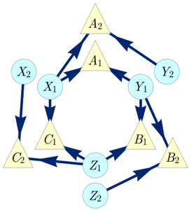
The image depicts a directed graph consisting of triangular and circular nodes, interconnected by arrows indicating the direction of relationships. The nodes are labeled with letters and numerical subscripts.
### Components/Axes
* **Nodes:**
* Triangular nodes: A1, A2, B1, B2, C1, C2. These are colored light yellow.
* Circular nodes: X1, X2, Y1, Y2, Z1, Z2. These are colored light blue.
* **Edges:** Arrows indicate the direction of the relationship between nodes. The arrows are dark blue.
### Detailed Analysis
The graph shows the following connections:
* A1: Connected to X1, Y1, and A2.
* A2: Connected to Y2 and B2.
* B1: Connected to Y1 and Z1.
* B2: Connected to Z2.
* C1: Connected to X1 and Z1.
* C2: Connected to X2.
* X1: Connected to C1.
* X2: Connected to C2.
* Y1: Connected to B1.
* Y2: Connected to A1.
* Z1: Connected to C2 and B2.
* Z2: Connected to Z1.
### Key Observations
* The graph has a cyclical structure involving A1, X1, C1, Z1, B1, and Y1.
* Nodes A2, B2, C2, X2, Y2, and Z2 appear to be peripheral, with fewer connections.
* Triangular nodes are connected to both triangular and circular nodes, while circular nodes primarily connect to triangular nodes.
### Interpretation
The diagram represents a network of relationships between different entities, potentially representing a system where the triangular nodes (A, B, C) and circular nodes (X, Y, Z) have distinct roles. The arrows indicate the direction of influence or flow between these entities. The cyclical structure suggests a feedback loop or recurring process within the system. The peripheral nodes (A2, B2, C2, X2, Y2, Z2) might represent inputs or outputs to the core cyclical process. The diagram could be used to model various systems, such as social networks, biological pathways, or economic models.