## Dataflow Diagram: Neural Network Accelerator Architecture
### Overview
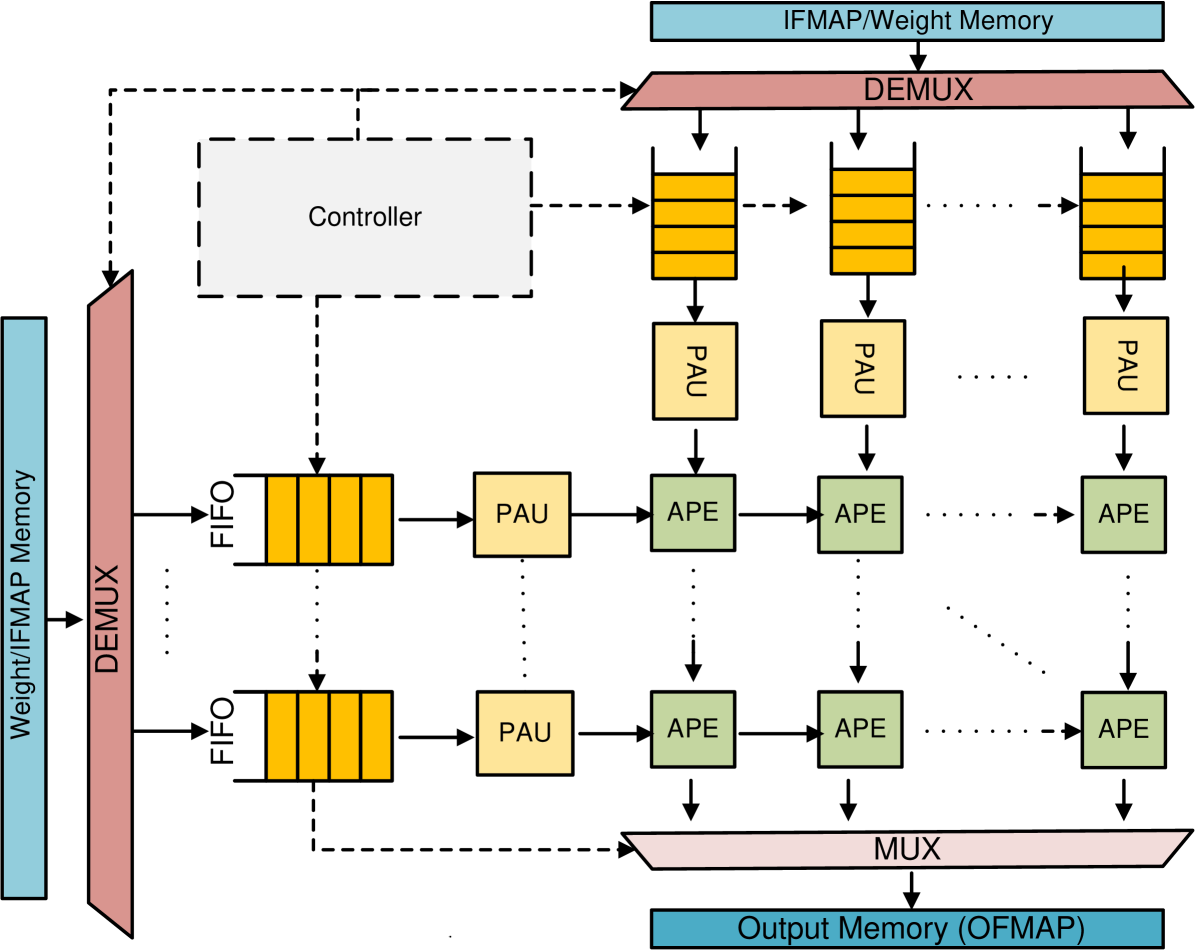
The image is a dataflow diagram illustrating the architecture of a neural network accelerator. It shows the flow of data from input memory through a series of processing units (PAU and APE) arranged in a grid-like structure, controlled by a central controller, and finally to output memory. The diagram highlights the parallel processing capabilities of the architecture.
### Components/Axes
* **Input Memory:** Labeled "Weight/IFMAP Memory" (light blue rectangle on the left and top). IFMAP likely stands for Input Feature Map.
* **Demultiplexer (DEMUX):** A pink trapezoid that splits the input data stream (located on the left and top).
* **First-In, First-Out (FIFO) Buffers:** Represented by yellow stacks of rectangles.
* **Processing Array Units (PAU):** Represented by yellow squares.
* **Arithmetic Processing Elements (APE):** Represented by green squares.
* **Multiplexer (MUX):** A pink trapezoid that combines the output data streams (located at the bottom).
* **Output Memory:** Labeled "Output Memory (OFMAP)" (light blue rectangle at the bottom). OFMAP likely stands for Output Feature Map.
* **Controller:** A dashed-line rectangle in the top-left, connected to various components with dashed lines, indicating control signals.
### Detailed Analysis
The diagram depicts a dataflow architecture with the following key elements:
1. **Input Data:** Data, likely weights and input feature maps (IFMAP), is read from the "Weight/IFMAP Memory". There are two input memories, one on the left and one on the top.
2. **Demultiplexing:** The "DEMUX" splits the input data stream into multiple parallel streams.
3. **FIFO Buffers:** The data streams are fed into "FIFO" buffers, which likely act as temporary storage to synchronize data flow. Each FIFO appears to hold 4 data elements.
4. **Processing Array Units (PAU):** The data from the FIFOs is processed by "PAU" units.
5. **Arithmetic Processing Elements (APE):** The output of the PAUs is then fed into a grid of "APE" units. The diagram shows a 3x2 grid of APEs, but the "..." notation indicates that the grid can be extended.
6. **Multiplexing:** The outputs of the APEs are combined by the "MUX".
7. **Output Data:** The final result is written to the "Output Memory (OFMAP)".
8. **Controller:** The "Controller" manages the data flow and processing within the architecture. It sends control signals (dashed lines) to the DEMUX, FIFOs, PAUs, and APEs.
The data flows from left to right and top to bottom. The dotted lines indicate that the PAU outputs are connected to the APEs in the next row.
### Key Observations
* The architecture is designed for parallel processing, with multiple PAUs and APEs operating simultaneously.
* The FIFO buffers likely play a crucial role in synchronizing data flow and handling variations in processing time.
* The controller is responsible for orchestrating the entire dataflow and ensuring correct operation.
### Interpretation
The diagram illustrates a hardware architecture optimized for neural network computations. The parallel arrangement of PAUs and APEs allows for efficient processing of large amounts of data, which is essential for deep learning applications. The use of FIFO buffers and a central controller ensures that the data flows smoothly and that the processing units are utilized effectively. The architecture is likely designed to accelerate matrix multiplications and other common neural network operations. The presence of separate input memories for weights and IFMAP suggests that the architecture is optimized for convolutional neural networks (CNNs).