## Diagram: State Transition and Logical Possibility Model
### Overview
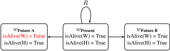
This image is a state transition diagram, likely representing a Kripke structure or a branching timeline in modal logic. It depicts a central "Present" state that branches into two distinct "Future" states, with a self-referential relation ($R$) defined for the present state. The diagram illustrates the truth values of two predicates, `isAlive(W)` and `isAlive(H)`, across these three states.
### Components/Axes
The diagram consists of three rectangular nodes connected by arrows, with text labels defining the state and the logical properties within each state.
* **Nodes (States):**
* **Center Node:** Labeled $w_{\text{Present}}$.
* **Left Node:** Labeled $w_{\text{Future A}}$.
* **Right Node:** Labeled $w_{\text{Future B}}$.
* **Transitions (Edges):**
* **Self-Loop:** An arrow originating from and returning to $w_{\text{Present}}$, labeled with $R$ at the apex.
* **Leftward Arrow:** A directed line from $w_{\text{Present}}$ to $w_{\text{Future A}}$.
* **Rightward Arrow:** A directed line from $w_{\text{Present}}$ to $w_{\text{Future B}}$.
* **Logical Predicates (Content):**
* `isAlive(W)`: A predicate regarding entity W.
* `isAlive(H)`: A predicate regarding entity H.
### Detailed Analysis
#### 1. Center Node ($w_{\text{Present}}$)
* **Position:** Center of the diagram.
* **Content:**
* `isAlive(W) = True`
* `isAlive(H) = True`
* **Dynamics:** Features a reflexive relation $R$ (a self-loop), suggesting that the present state is accessible from itself.
#### 2. Left Node ($w_{\text{Future A}}$)
* **Position:** Left of the center node.
* **Content:**
* `isAlive(W) = False` (Note: This text is colored **red**).
* `isAlive(H) = True`
* **Dynamics:** Accessible from $w_{\text{Present}}$.
#### 3. Right Node ($w_{\text{Future B}}$)
* **Position:** Right of the center node.
* **Content:**
* `isAlive(W) = True`
* `isAlive(H) = True`
* **Dynamics:** Accessible from $w_{\text{Present}}$.
### Key Observations
* **Branching Logic:** The diagram demonstrates a bifurcation of possibilities originating from $w_{\text{Present}}$.
* **The "Red" Anomaly:** The value `isAlive(W) = False` in $w_{\text{Future A}}$ is highlighted in red. This visually distinguishes this specific outcome from all other truth values in the diagram, which are rendered in black.
* **Consistency:** The predicate `isAlive(H)` remains `True` across all three states, suggesting that entity H is unaffected by the transitions, whereas entity W is the variable component.
* **Symmetry:** The transition to $w_{\text{Future B}}$ represents a "status quo" outcome where the truth values of the present are preserved, while the transition to $w_{\text{Future A}}$ represents a change in the state of W.
### Interpretation
This diagram is a formal representation of a decision tree or a modal logic scenario, often used to model counterfactuals or branching timelines.
* **Logical Implication:** The diagram suggests that from the current state ($w_{\text{Present}}$), there are two possible future paths. One path ($w_{\text{Future B}}$) maintains the current state of affairs. The other path ($w_{\text{Future A}}$) results in the negation of the predicate `isAlive(W)`.
* **The Role of Red Text:** The use of red for `isAlive(W) = False` serves as a visual signifier, likely indicating a "death" event or a critical failure state. It draws the viewer's attention to the specific branch where the entity W ceases to be "alive."
* **Peircean Investigative Perspective:**
* **The Sign:** The diagram acts as an icon of a branching timeline.
* **The Object:** The underlying reality is a system where entity W's survival is contingent or probabilistic, while entity H's survival is constant.
* **The Interpretant:** The viewer is meant to understand that the "Present" is a state of superposition or uncertainty, where the future is not yet determined, but the possibilities are constrained to either the survival or the death of W. The self-loop $R$ suggests that the present state is stable or persistent until a transition occurs.