## Diagram: Service Interaction Architecture
### Overview
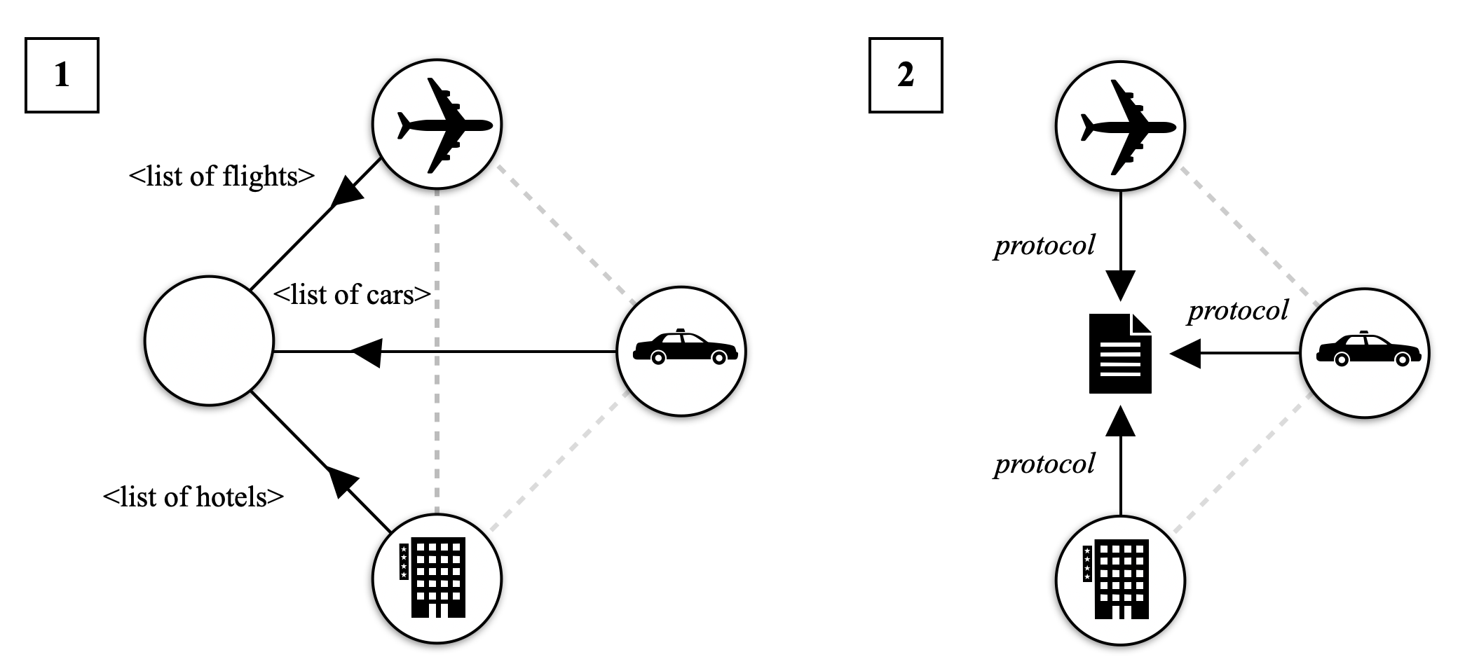
The image contains two labeled diagrams (1 and 2) depicting a system architecture with interconnected components. Diagram 1 shows a central node connected to three service nodes (airplane, car, hotel) via labeled arrows. Diagram 2 introduces a "protocol" document as a central node with bidirectional dashed arrows to the same service nodes.
### Components/Axes
- **Diagram 1**:
- **Central Node**: Unlabeled, acts as a hub.
- **Service Nodes**:
- Airplane (icon: airplane)
- Car (icon: car)
- Hotel (icon: building)
- **Arrows**:
- Solid black arrows from the central node to each service node.
- Labels on arrows:
- `<list of flights>` (to airplane)
- `<list of cars>` (to car)
- `<list of hotels>` (to hotel)
- **Diagram 2**:
- **Central Node**: Labeled "protocol" (icon: document).
- **Service Nodes**: Same as Diagram 1 (airplane, car, hotel).
- **Arrows**:
- Dashed gray arrows connecting the protocol node to each service node.
- Labels on arrows: "protocol" (bidirectional).
### Detailed Analysis
- **Diagram 1**:
- The central node distributes three distinct data lists (`<list of flights>`, `<list of cars>`, `<list of hotels>`) to their respective service nodes.
- Arrows are unidirectional, suggesting a one-way flow of information from the central node to services.
- **Diagram 2**:
- The "protocol" document serves as a mediator, with bidirectional dashed arrows to all service nodes.
- Dashed arrows imply optional, indirect, or governance-related interactions rather than direct data exchange.
### Key Observations
1. **Centralization**: Both diagrams emphasize a central node (either the hub or protocol document) as the focal point of interactions.
2. **Data Flow**: Diagram 1 focuses on data distribution, while Diagram 2 emphasizes governance or standardization via protocols.
3. **Dashed vs. Solid Arrows**: Solid arrows in Diagram 1 suggest mandatory data exchange, whereas dashed arrows in Diagram 2 indicate advisory or optional relationships.
### Interpretation
- **System Functionality**:
- Diagram 1 likely represents a travel booking system where a central agency provides curated lists of flights, cars, and hotels to users or downstream services.
- Diagram 2 introduces a protocol layer, suggesting standardized rules or agreements governing interactions between the central system and external services (e.g., API specifications, data formats).
- **Relationships**:
- The protocol document in Diagram 2 acts as a bridge, ensuring consistency across services. For example, flight booking protocols might dictate how flight data is structured or validated.
- Dashed arrows could represent feedback loops or compliance checks (e.g., hotels adhering to protocol standards).
- **Anomalies/Outliers**:
- No explicit outliers, but the shift from solid to dashed arrows between diagrams highlights a conceptual transition from data provision to governance.
- **Underlying Logic**:
- The architecture prioritizes modularity, with services (airplane, car, hotel) operating independently but governed by shared protocols.
- The central node in Diagram 1 may represent a database or API gateway, while the protocol node in Diagram 2 could symbolize a rule engine or compliance framework.