## Diagram: Barrel Shifter Architecture
### Overview
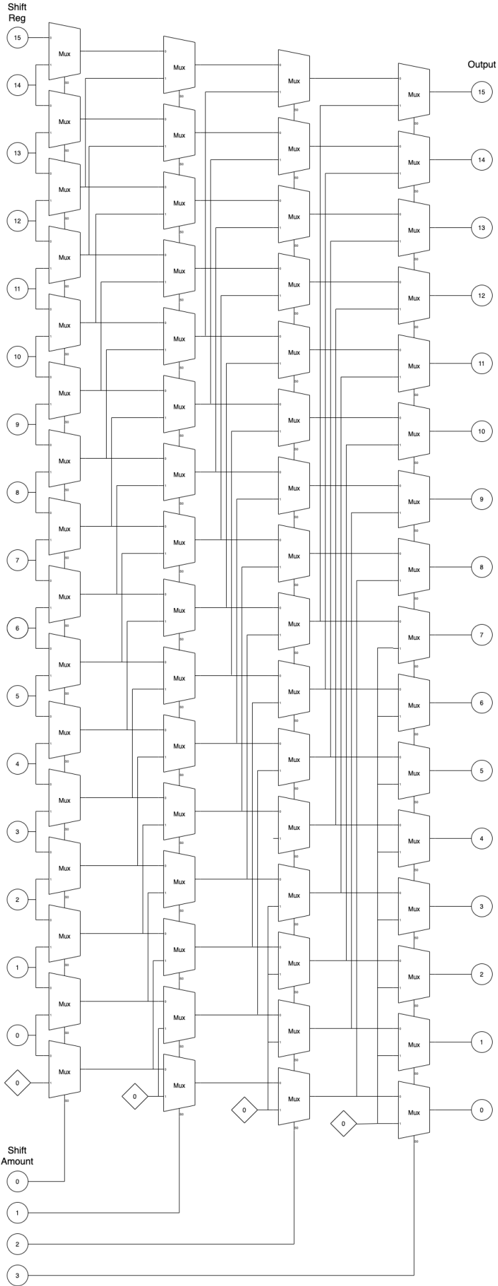
The image depicts a barrel shifter architecture, a digital circuit that can shift a data word by a specified number of bits without using any sequential logic, only combinational logic. The diagram shows a 16-bit barrel shifter implemented using multiple stages of multiplexers (Mux). The shift amount is controlled by the input at the bottom, and the output is the shifted data at the top.
### Components/Axes
* **Shift Reg:** (Shift Register) - Labeled on the top-left. Represents the input data to be shifted. Values range from 0 to 15, arranged vertically.
* **Output:** Labeled on the top-right. Represents the output data after shifting. Values range from 0 to 15, arranged vertically.
* **Shift Amount:** Labeled on the bottom-left. Represents the amount by which the input data is shifted. Values range from 0 to 3, arranged vertically.
* **Mux:** (Multiplexer) - Labeled on each multiplexer component.
* **Diamonds with "0":** These represent a constant input of 0 to the multiplexers.
### Detailed Analysis
The diagram consists of several columns of multiplexers. Each multiplexer selects between two inputs based on the shift amount. The shift amount inputs (0-3) control the selection of the multiplexers in each stage.
* **Input Stage (Shift Reg):** The input data is labeled from 0 to 15, arranged vertically on the left side. Each input is connected to the first column of multiplexers.
* **Multiplexer Stages:** There are multiple columns of multiplexers. Each multiplexer has two inputs: one from the previous stage and one from a shifted position. The shift amount determines which input is selected.
* **Shift Amount Control:** The shift amount inputs (0, 1, 2, 3) at the bottom control the selection of the multiplexers in each stage. The diamond shapes with "0" inside represent a constant input of 0 to the multiplexers.
* **Output Stage:** The output data is labeled from 0 to 15, arranged vertically on the right side. Each output is connected to the last column of multiplexers.
**Detailed Connections:**
* **Shift Amount 0:** When the shift amount is 0, the multiplexers select the input directly from the previous stage, resulting in no shift.
* **Shift Amount 1:** When the shift amount is 1, the multiplexers select the input shifted by one position.
* **Shift Amount 2:** When the shift amount is 2, the multiplexers select the input shifted by two positions.
* **Shift Amount 3:** The diagram does not explicitly show the connections for shift amount 3, but it can be inferred that the multiplexers would select the input shifted by three positions.
### Key Observations
* The diagram illustrates a 16-bit barrel shifter architecture.
* The shift amount is controlled by the input at the bottom.
* The output is the shifted data at the top.
* The multiplexers select between two inputs based on the shift amount.
* The diamond shapes with "0" inside represent a constant input of 0 to the multiplexers.
### Interpretation
The barrel shifter architecture allows for efficient shifting of data by a specified number of bits. The multiplexers select between different shifted positions based on the shift amount. This architecture is commonly used in digital circuits for various applications, such as data processing, signal processing, and cryptography. The use of multiplexers allows for a fast and efficient implementation of the shift operation. The diagram provides a clear representation of the barrel shifter architecture and its components.