## Diagram: Binary Matrix Multiplication with LUT-Based Accumulation
### Overview
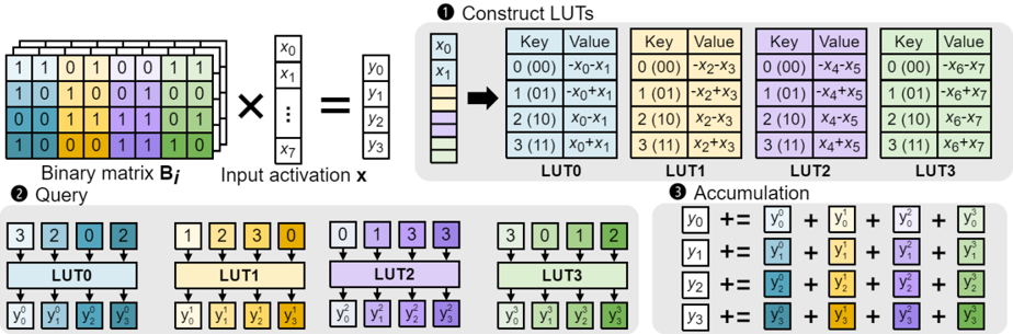
The diagram illustrates a computational process involving binary matrix multiplication, Look-Up Table (LUT) construction, and accumulation of results. It demonstrates how input activations are transformed through a series of logical operations and combined to produce final output values.
### Components/Axes
1. **Binary Matrix Bi** (Top-left):
- 4x8 binary matrix with values 0/1
- Rows labeled 1-4, columns labeled 0-7
- Color-coded cells (green, blue, yellow, purple) indicate different binary values
2. **Input Activation x** (Right of matrix):
- 8-dimensional vector (x₀ to x₇)
- Represented as vertical column with binary values
3. **Output y** (Right of matrix multiplication):
- 4-dimensional vector (y₀ to y₃)
- Result of matrix-vector multiplication
4. **LUT Construction** (Middle section):
- Four LUTs (LUT0-LUT3) with Key-Value pairs
- Keys: 2-bit binary combinations (00, 01, 10, 11)
- Values: Boolean expressions involving input bits (e.g., -x₀-x₁, x₀+x₁)
5. **Accumulation** (Bottom section):
- Four output lines (y₀ to y₃)
- Each yᵢ is sum of corresponding LUT outputs
- Color-coded contributions from each LUT
6. **Legend** (Bottom-right):
- Color coding for LUTs:
- LUT0: Light blue
- LUT1: Beige
- LUT2: Purple
- LUT3: Green
### Detailed Analysis
1. **Matrix Multiplication**:
- Binary matrix Bi (4x8) multiplied by input vector x (8x1)
- Resulting output y (4x1) shown as vertical column
- Example: y₀ = (1·x₀) + (1·x₁) + (0·x₂) + ... + (1·x₇)
2. **LUT Construction**:
- LUT0:
- 0000 → -x₀-x₁
- 0001 → -x₀+x₁
- 0010 → x₀-x₁
- 0011 → x₀+x₁
- Similar patterns for LUT1-LUT3 with different bit combinations
3. **Accumulation**:
- y₀ = y₀(LUT0) + y₀(LUT1) + y₀(LUT2) + y₀(LUT3)
- Color-coded contributions match LUT legend
- Example: y₁ = (blue) + (yellow) + (purple) + (green)
### Key Observations
1. Non-linear transformation through LUTs enables complex bitwise operations
2. Accumulation combines multiple LUT outputs for final result
3. Color coding provides visual separation of LUT contributions
4. Binary operations suggest potential application in digital signal processing
### Interpretation
This diagram represents a hybrid computational architecture combining:
1. Linear algebra operations (matrix multiplication)
2. Non-linear transformations (LUT-based)
3. Parallel accumulation for final output
The use of LUTs allows for:
- Efficient implementation of complex bitwise operations
- Flexible reconfiguration through LUT value changes
- Parallel processing of multiple input combinations
The color-coded accumulation visually demonstrates how different LUTs contribute to each output dimension, suggesting this could be part of a neural network layer or specialized hardware accelerator for binary data processing.