## Diagram: Input-to-Output Transformation Flow
### Overview
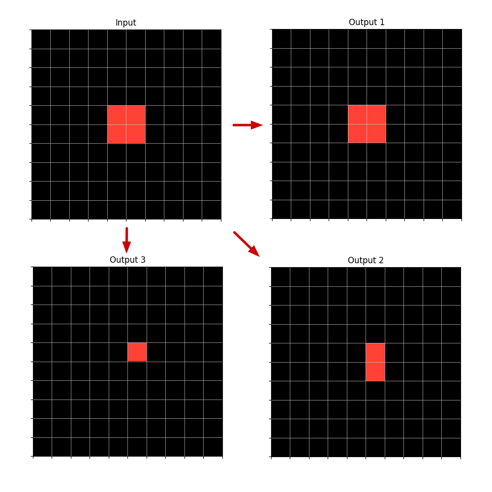
The image displays a technical diagram illustrating a transformation process from a single input state to three distinct output states. The diagram consists of four 10x10 grid matrices, each representing a 2D spatial field. A red highlighted region within each grid represents a "foreground" or "active" area. Red arrows indicate the directional flow of transformation from the "Input" to each of the three "Outputs."
### Components/Axes
* **Grid Structure:** Four separate 10x10 grids. Each grid cell is demarcated by thin white lines on a black background.
* **Labels:**
* **Input:** Located top-left.
* **Output 1:** Located top-right.
* **Output 2:** Located bottom-right.
* **Output 3:** Located bottom-left.
* **Flow Indicators:** Three solid red arrows.
* One arrow points horizontally from the right edge of the "Input" grid to the left edge of the "Output 1" grid.
* One arrow points vertically downward from the bottom edge of the "Input" grid to the top edge of the "Output 3" grid.
* One arrow points diagonally from the bottom-right corner of the "Input" grid to the top-left corner of the "Output 2" grid.
* **Data Representation:** The "data" is the spatial configuration of red-filled cells within each grid. No numerical axes, scales, or legends are present.
### Detailed Analysis
**1. Input Grid (Top-Left):**
* Contains a solid red 2x2 square block.
* **Spatial Position:** The block is centered within the grid. Assuming a 1-indexed grid from the top-left, the red cells occupy rows 5-6 and columns 5-6.
**2. Output 1 Grid (Top-Right):**
* Contains a solid red 2x2 square block, identical in size and shape to the Input.
* **Spatial Position:** The block is also centered, occupying rows 5-6 and columns 5-6.
* **Transformation from Input:** No change in shape, size, or position. The horizontal arrow suggests a direct copy or identity operation.
**3. Output 2 Grid (Bottom-Right):**
* Contains a solid red vertical rectangle of size 1x2 (1 cell wide, 2 cells tall).
* **Spatial Position:** The rectangle is centered horizontally but spans rows 5-6 in column 5.
* **Transformation from Input:** The 2x2 square has been reduced to a 1x2 vertical line. The diagonal arrow suggests a transformation that reduces horizontal dimension while preserving vertical extent in the leftmost column of the original shape.
**4. Output 3 Grid (Bottom-Left):**
* Contains a single red cell.
* **Spatial Position:** The cell is located at row 5, column 5.
* **Transformation from Input:** The 2x2 square has been reduced to its top-left corner cell. The vertical arrow suggests a transformation that reduces the shape to a single point, specifically the origin (top-left) of the original bounding box.
### Key Observations
* **Consistent Origin Point:** All output shapes are anchored to the top-left cell (row 5, column 5) of the original 2x2 input square.
* **Progressive Reduction:** The outputs show a hierarchy of reduction: Output 1 (no reduction) -> Output 2 (50% reduction, vertical axis preserved) -> Output 3 (75% reduction, single point).
* **Directional Semantics:** The arrow directions may symbolically correspond to the type of transformation: horizontal (identity/copy), vertical (column-wise reduction), and diagonal (point-wise reduction).
### Interpretation
This diagram likely illustrates fundamental operations in image processing, matrix manipulation, or cellular automata. The transformations demonstrate:
1. **Identity Operation (Output 1):** The input is passed through unchanged.
2. **Morphological Erosion or Projection (Output 2):** The input is eroded to a vertical line, possibly representing a projection onto the Y-axis or the result of a vertical structuring element.
3. **Downsampling or Feature Extraction (Output 3):** The input is reduced to a single representative point, such as its centroid (approximated here as the top-left corner) or a downsampled pixel.
The diagram serves as a visual specification for how a system should decompose or simplify a 2D input pattern based on different rules or pathways. The clear spatial grounding allows for precise reconstruction of the intended logic without ambiguity.