## State Diagram: Finite State Machine
### Overview
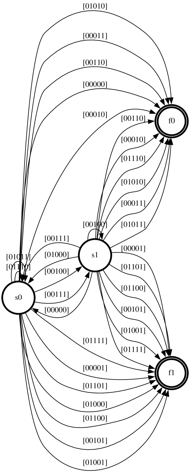
The image depicts a state diagram representing a finite state machine (FSM). The diagram shows three states (s0, s1, f0, f1) and the transitions between them, labeled with binary strings. The diagram appears to model a sequential logic circuit or a stateful process.
### Components/Axes
The diagram consists of:
* **States:** Represented by circles labeled 's0', 's1', 'f0', and 'f1'.
* **Transitions:** Represented by directed arrows connecting the states, labeled with 5-bit binary strings.
* **Initial State:** 's0' is the initial state, indicated by the incoming arrow without a source state.
### Detailed Analysis or Content Details
The diagram shows the following transitions:
**From s0:**
* To s1: labeled "[01011]", "[00111]", "[01000]", "[00101]", "[00010]", "[00001]", "[00100]", "[01101]", "[00000]", "[01111]", "[00110]", "[01001]"
* To f0: labeled "[01010]"
**From s1:**
* To f0: labeled "[00111]", "[01000]", "[00101]", "[00010]", "[00001]", "[01101]", "[01011]", "[00000]", "[01111]", "[00110]", "[01001]"
* To f1: labeled "[00100]", "[00000]", "[01111]", "[00110]", "[01001]"
**From f0:**
* To f1: labeled "[00110]", "[00101]", "[01110]", "[01010]", "[00011]", "[01011]", "[00001]", "[01101]", "[01100]", "[00101]", "[00101]", "[01001]"
**From f1:**
* To s0: labeled "[01111]", "[00111]", "[01101]", "[01001]", "[01100]", "[00101]", "[01001]", "[01001]", "[00101]", "[01001]"
### Key Observations
* The state 's0' has the most incoming transitions, suggesting it's a common destination.
* The state 'f1' has only outgoing transitions, leading back to 's0'.
* The transitions are labeled with binary strings, which likely represent input values or conditions.
* The diagram is fully connected, meaning every state can transition to every other state (or back to itself) given the appropriate input.
### Interpretation
This state diagram likely represents a digital circuit or a control system. The binary strings on the transitions represent the input conditions that cause the system to move from one state to another. The diagram suggests a cyclical behavior, where the system transitions through the states 's0', 's1', 'f0', and 'f1' repeatedly based on the input sequence.
The diagram could be a model for:
* **A sequence detector:** The FSM might be designed to recognize a specific sequence of binary inputs.
* **A counter:** The states could represent different count values, and the transitions could be triggered by clock pulses.
* **A control logic:** The FSM could be part of a larger system that controls the behavior of other components.
The fully connected nature of the diagram suggests a flexible system that can respond to a wide range of inputs. The specific meaning of the states and transitions would depend on the context in which the FSM is used. The diagram is a formal representation of a dynamic system, allowing for analysis and verification of its behavior. The diagram is a visual representation of a mathematical model, and can be used to simulate and understand the system's behavior.