## Carry Lookahead Adder Diagram
### Overview
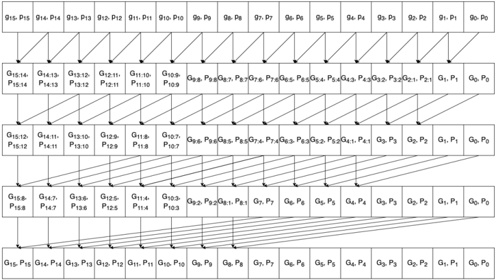
The image is a schematic diagram illustrating the structure of a carry-lookahead adder. It shows the propagation and generation of carry signals across multiple stages of addition. The diagram uses blocks to represent the generation and propagation of carry signals, and arrows to indicate the flow of these signals.
### Components/Axes
The diagram consists of several rows of blocks, each representing a stage in the carry-lookahead adder. Each block contains two variables, G and P, representing the generate and propagate signals, respectively. The subscripts indicate the bit positions involved in the calculation. Arrows connect the blocks, showing the flow of carry signals.
* **Blocks:** Each block contains "G" and "P" values, representing carry generate and propagate signals. The subscripts indicate the bit positions involved.
* **Arrows:** Arrows indicate the flow of carry signals between blocks.
* **Rows:** The diagram has 5 rows, each representing a stage of carry generation and propagation.
### Detailed Analysis or ### Content Details
**Row 1:**
* The first row contains blocks labeled as "G15, P15" to "G0, P0".
* The blocks are arranged horizontally from left to right.
* The subscripts decrease from 15 to 0.
**Row 2:**
* The second row contains blocks labeled as "G15:14, P15:14" to "G0, P0".
* The blocks are arranged horizontally from left to right.
* The subscripts decrease from 15:14 to 0.
* Arrows connect each block in the first row to a block in the second row. The arrows point diagonally downwards and to the right.
**Row 3:**
* The third row contains blocks labeled as "G15:12, P15:12" to "G0, P0".
* The blocks are arranged horizontally from left to right.
* The subscripts decrease from 15:12 to 0.
* Arrows connect each block in the second row to a block in the third row. The arrows point diagonally downwards and to the right.
**Row 4:**
* The fourth row contains blocks labeled as "G15:8, P15:8" to "G0, P0".
* The blocks are arranged horizontally from left to right.
* The subscripts decrease from 15:8 to 0.
* Arrows connect each block in the third row to a block in the fourth row. The arrows point diagonally downwards and to the right.
**Row 5:**
* The fifth row contains blocks labeled as "G15, P15" to "G0, P0".
* The blocks are arranged horizontally from left to right.
* The subscripts decrease from 15 to 0.
* Arrows connect each block in the fourth row to a block in the fifth row. The arrows point downwards.
**Specific Block Labels:**
* Row 1: G15, P15; G14, P14; G13, P13; G12, P12; G11, P11; G10, P10; G9, P9; G8, P8; G7, P7; G6, P6; G5, P5; G4, P4; G3, P3; G2, P2; G1, P1; G0, P0
* Row 2: G15:14, P15:14; G14:13, P14:13; G13:12, P13:12; G12:11, P12:11; G11:10, P11:10; G10:9, P10:9; G9:8, P9:8; G8:7, P8:7; G7:6, P7:6; G6:5, P6:5; G5:4, P5:4; G4:3, P4:3; G3:2, P3:2; G2:1, P2:1; G1, P1; G0, P0
* Row 3: G15:12, P15:12; G14:11, P14:11; G13:10, P13:10; G12:9, P12:9; G11:8, P11:8; G10:7, P10:7; G9:6, P9:6; G8:5, P8:5; G7:4, P7:4; G6:3, P6:3; G5:2, P5:2; G4:1, P4:1; G3, P3; G2, P2; G1, P1; G0, P0
* Row 4: G15:8, P15:8; G14:7, P14:7; G13:6, P13:6; G12:5, P12:5; G11:4, P11:4; G10:3, P10:3; G9:2, P9:2; G8:1, P8:1; G7, P7; G6, P6; G5, P5; G4, P4; G3, P3; G2, P2; G1, P1; G0, P0
* Row 5: G15, P15; G14, P14; G13, P13; G12, P12; G11, P11; G10, P10; G9, P9; G8, P8; G7, P7; G6, P6; G5, P5; G4, P4; G3, P3; G2, P2; G1, P1; G0, P0
### Key Observations
* The diagram illustrates a hierarchical structure for carry generation and propagation.
* The carry signals are combined across multiple bit positions in each stage.
* The final row represents the carry signals for each bit position.
### Interpretation
The diagram shows the architecture of a carry-lookahead adder, which is a type of adder used in digital circuits to improve speed by reducing the delay associated with carry propagation. The diagram illustrates how carry signals are generated and propagated across multiple stages, allowing for faster addition compared to ripple-carry adders. The hierarchical structure allows for parallel computation of carry signals, which significantly reduces the overall addition time.