## Diagram: Magnetic Coupling
### Overview
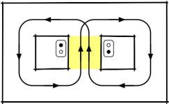
The image is a diagram illustrating magnetic coupling between two devices. It shows two rectangular objects, presumably electronic devices, with a yellow highlighted region between them. Curved arrows indicate the direction of the magnetic field lines circulating around the devices and coupling them together.
### Components/Axes
* **Devices:** Two rectangular objects, each with two circular elements on one side, possibly representing coils or antennas.
* **Magnetic Field Lines:** Curved arrows indicating the direction of the magnetic field.
* **Coupling Region:** A yellow highlighted rectangular area between the two devices, indicating the region of magnetic coupling.
* **Arrows:** Indicate the direction of the magnetic field lines.
### Detailed Analysis
The diagram shows two devices placed side-by-side. Each device has a square outline with two circular elements on one side. The yellow highlighted region between the devices indicates the area where magnetic coupling occurs. The curved arrows show the magnetic field lines emanating from one device, looping around, and entering the other device, and vice versa. The arrows indicate the direction of the magnetic field.
### Key Observations
* The magnetic field lines circulate around each device and couple them together.
* The yellow highlighted region indicates the area of strongest magnetic coupling.
* The direction of the arrows indicates the direction of the magnetic field.
### Interpretation
The diagram illustrates the concept of magnetic coupling between two devices. The magnetic field generated by one device interacts with the other device, allowing energy or information to be transferred between them. The yellow highlighted region indicates the area where the magnetic field is strongest and the coupling is most effective. This type of coupling is used in various applications, such as wireless power transfer and near-field communication (NFC).