\n
## Diagram: Electrical Wiring Configuration
### Overview
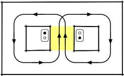
The image depicts a diagram illustrating the electrical wiring configuration between two electrical outlets. It shows the flow of current between the outlets, with a highlighted area indicating a potential issue or area of concern. The diagram is a simplified representation of a common electrical setup.
### Components/Axes
The diagram consists of the following components:
* **Two Electrical Outlets:** Represented as rectangular boxes with two circular openings each, indicating the sockets.
* **Current Flow Arrows:** Black arrows indicating the direction of electrical current flow around each outlet and between them.
* **Highlighted Area:** A yellow-colored area between the two outlets, suggesting a potential area of high current or a neutral connection.
* **Outer Rectangle:** A black rectangle outlining the entire diagram.
There are no axes or scales present in this diagram.
### Detailed Analysis or Content Details
The diagram shows a closed-loop current flow around each outlet. The arrows indicate that current enters one side of each outlet, flows through the device plugged into the outlet, and then returns to the other side of the outlet.
The key feature is the yellow highlighted area between the two outlets. Two upward-pointing arrows within this area suggest a direct current path between the neutral connections of the two outlets. This configuration is not standard and can cause issues.
The current flow around the left outlet is clockwise, while the current flow around the right outlet is also clockwise. The arrows connecting the two outlets indicate a current path between the neutral terminals.
### Key Observations
* The diagram highlights a potentially problematic wiring configuration where the neutral wires of the two outlets are directly connected.
* The closed-loop current flow around each outlet indicates a standard electrical circuit.
* The absence of any grounding wire representation is notable.
### Interpretation
The diagram likely illustrates a wiring error known as a "multi-wire branch circuit" issue, or potentially a bootleg neutral. This occurs when the neutral wires of two circuits are connected, creating a path for current to flow between them. This can lead to several problems:
* **Overloading:** If one circuit is heavily loaded, the current can flow through the neutral of the other circuit, potentially overloading it.
* **Voltage Imbalance:** Uneven loading can cause voltage imbalances, affecting the performance of connected devices.
* **Safety Hazard:** In some cases, this configuration can create a safety hazard, potentially leading to electrical shock or fire.
The yellow highlighted area emphasizes the problematic connection between the neutral wires. The diagram serves as a warning about the dangers of improper wiring and the importance of following electrical codes. The diagram is a simplified representation and does not include details like wire gauge, breaker size, or grounding. It is intended to illustrate a specific wiring issue rather than a complete electrical installation.