## Diagram: Neural Network and Memristor Crossbar Array
### Overview
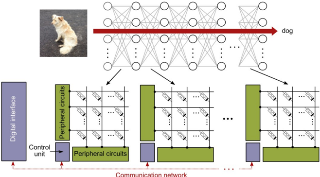
The image depicts a neural network architecture and its implementation using a memristor crossbar array. The diagram illustrates the flow of information from an input image (a dog) through the neural network layers to an output classification ("dog"). The neural network's connections are then mapped onto a physical memristor crossbar array for hardware implementation.
### Components/Axes
* **Input:** Image of a dog (top-left)
* **Neural Network:** A multi-layered neural network with interconnected nodes (circles). The connections between layers are represented by lines.
* **Output:** "dog" (top-right), indicating the classification result.
* **Memristor Crossbar Array:** A grid-like structure composed of horizontal and vertical lines, with memristors (represented by resistor symbols) at the intersections.
* **Digital Interface:** A blue block labeled "Digital interface" on the left.
* **Control Unit:** A blue block labeled "Control unit" below the digital interface.
* **Peripheral Circuits:** Green blocks labeled "Peripheral circuits" surrounding the memristor arrays.
* **Communication Network:** A dotted red line labeled "Communication network" at the bottom.
* **Arrows:** Arrows indicate the flow of information from the neural network layers to the memristor arrays.
### Detailed Analysis
* **Neural Network Structure:** The neural network consists of multiple layers of interconnected nodes. The connections between nodes represent the weights of the neural network. A red arrow highlights a specific path through the network, leading to the "dog" output.
* **Memristor Array Mapping:** The connections of the neural network are mapped onto the memristor crossbar array. Each memristor represents a synaptic weight in the neural network. The peripheral circuits provide the necessary control and read/write operations for the memristor array.
* **Digital Interface and Control Unit:** The digital interface provides the input to the neural network and receives the output. The control unit manages the operation of the memristor array.
* **Communication Network:** The communication network facilitates data transfer between the different components of the system.
* **Array Structure:** Each memristor array is connected to peripheral circuits on the top and right sides. A control unit is connected to the bottom of the peripheral circuits. The digital interface is connected to the control unit.
### Key Observations
* The diagram illustrates the concept of implementing a neural network using memristor technology.
* The memristor crossbar array provides a compact and energy-efficient way to implement the synaptic weights of the neural network.
* The peripheral circuits and control unit are essential for managing the operation of the memristor array.
### Interpretation
The diagram demonstrates how a neural network can be physically realized using a memristor crossbar array. This approach offers potential advantages in terms of power consumption, speed, and scalability compared to traditional software-based implementations. The memristor array acts as a hardware accelerator for the neural network, enabling faster and more efficient processing of data. The diagram highlights the key components and their interactions in this type of system, showcasing the integration of neural network algorithms with emerging hardware technologies. The use of memristors to represent synaptic weights allows for a dense and energy-efficient implementation of neural networks, which is particularly relevant for applications in edge computing and artificial intelligence.