## Diagram: Barrel Shifter
### Overview
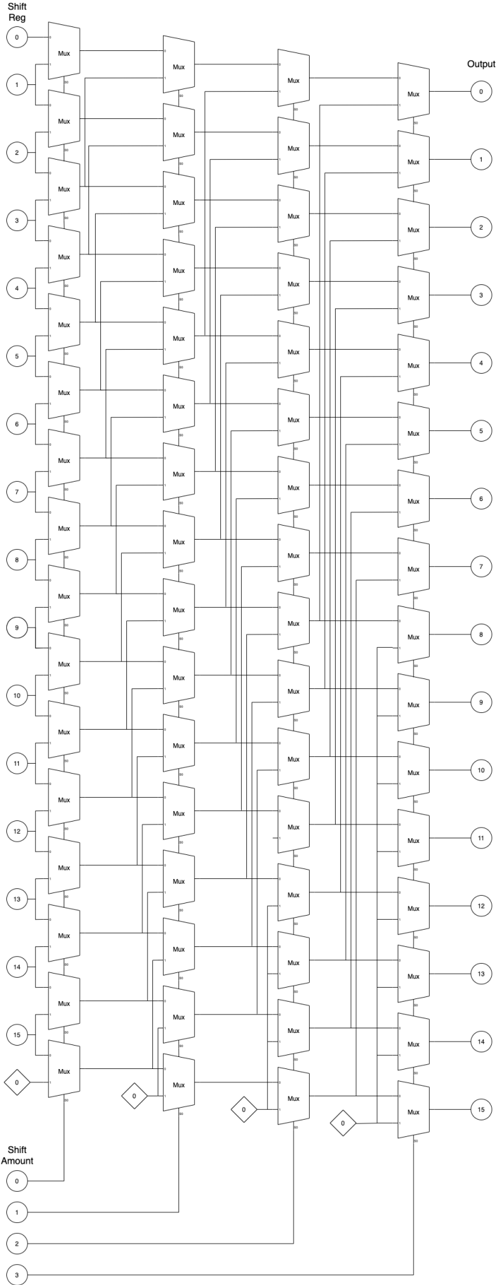
The image is a schematic diagram of a 16-bit barrel shifter implemented using multiplexers (Mux). It shows how the input bits are shifted based on the shift amount. The diagram consists of multiple stages of multiplexers arranged in columns, with connections indicating the data flow for different shift amounts.
### Components/Axes
* **Shift Reg:** (Top-left) Input register with 16 bits, labeled 0 to 15.
* **Output:** (Top-right) Output register with 16 bits, labeled 0 to 15.
* **Mux:** Multiplexer component, repeated throughout the diagram.
* **Shift Amount:** (Bottom-left) Shift amount input, labeled 0 to 3.
* **Diamonds:** Control signals for the multiplexers, labeled "0".
### Detailed Analysis
The diagram shows a multi-stage arrangement of multiplexers. Each stage corresponds to a different power of 2 shift (1, 2, 4, 8).
* **Input (Shift Reg):** The input is a 16-bit register, with each bit labeled from 0 to 15, positioned vertically on the left side of the diagram. Each bit is connected to the first column of multiplexers.
* **Multiplexers (Mux):** The diagram uses multiple columns of multiplexers. Each multiplexer has two inputs and one output. The control signal for each multiplexer determines which input is passed to the output. The multiplexers are arranged in a grid-like structure.
* **Shift Amount:** The shift amount is controlled by the input at the bottom of the diagram, labeled 0 to 3. These inputs control the selection lines of the multiplexers.
* **Control Signals:** The diamond shapes labeled "0" represent control signals that determine the selection of the multiplexers.
* **Output:** The output is a 16-bit register, with each bit labeled from 0 to 15, positioned vertically on the right side of the diagram. Each bit is the output of the last column of multiplexers.
**Data Flow:**
The data flows from left to right. The input bits from the "Shift Reg" are fed into the first column of multiplexers. Based on the "Shift Amount" and the control signals, the multiplexers select the appropriate input and pass it to the next stage. This process continues through each column of multiplexers until the final shifted output is obtained at the "Output" register.
**Specific Connections:**
* The first column of multiplexers takes the input from the "Shift Reg".
* The second column of multiplexers takes the output from the first column.
* The third column of multiplexers takes the output from the second column.
* The fourth column of multiplexers takes the output from the third column.
* The output of the fourth column is the final shifted output.
### Key Observations
* The diagram illustrates a 16-bit barrel shifter.
* The shifter is implemented using multiplexers.
* The shift amount is controlled by the input at the bottom of the diagram.
* The control signals determine the selection of the multiplexers.
* The data flows from left to right through the multiplexer stages.
### Interpretation
The diagram demonstrates how a barrel shifter can be implemented using multiplexers. A barrel shifter is a digital circuit that can shift a data word by a specified number of bits without using any sequential logic, making it faster than shift registers for multi-bit shifts. The arrangement of multiplexers allows for efficient shifting of the input bits based on the shift amount. The control signals determine the specific connections and data flow required to achieve the desired shift. The diagram provides a clear visual representation of the internal workings of a barrel shifter, highlighting the role of multiplexers in achieving the shifting functionality.