## Multiplication Diagram: Binary Multiplication
### Overview
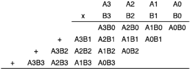
The image depicts the multiplication of two 4-bit binary numbers, A and B, using the standard multiplication algorithm. It shows the partial products generated by multiplying each bit of B with the entire number A, and then summing these partial products to obtain the final result.
### Components/Axes
* **Top Row:** A3, A2, A1, A0 (representing the bits of number A, from most significant to least significant)
* **Second Row:** x, B3, B2, B1, B0 (representing the bits of number B, from most significant to least significant, with 'x' indicating multiplication)
* **Partial Products:**
* A3B0, A2B0, A1B0, A0B0 (A multiplied by B0)
* A3B1, A2B1, A1B1, A0B1 (A multiplied by B1)
* A3B2, A2B2, A1B2, A0B2 (A multiplied by B2)
* A3B3, A2B3, A1B3, A0B3 (A multiplied by B3)
* **'+' signs:** Indicate the addition of the partial products.
### Detailed Analysis or ### Content Details
The diagram illustrates the multiplication process as follows:
1. **First Partial Product:** A is multiplied by B0, resulting in A3B0, A2B0, A1B0, A0B0.
2. **Second Partial Product:** A is multiplied by B1, resulting in A3B1, A2B1, A1B1, A0B1. This partial product is shifted one position to the left.
3. **Third Partial Product:** A is multiplied by B2, resulting in A3B2, A2B2, A1B2, A0B2. This partial product is shifted two positions to the left.
4. **Fourth Partial Product:** A is multiplied by B3, resulting in A3B3, A2B3, A1B3, A0B3. This partial product is shifted three positions to the left.
The '+' signs indicate that these partial products are then added together to obtain the final product.
### Key Observations
* The diagram clearly shows the bitwise multiplication and the necessary left shifts for each partial product.
* The representation uses symbolic notation (A3B0, etc.) to represent the AND operation between the corresponding bits of A and B.
### Interpretation
The diagram demonstrates the standard algorithm for binary multiplication. Each partial product is generated by performing a bitwise AND operation between the bits of the multiplicand (A) and a single bit of the multiplier (B). The partial products are then shifted left by an amount corresponding to the bit position of the multiplier and added together. This process is fundamental to digital arithmetic and is implemented in hardware multipliers within computer systems. The diagram provides a visual representation of this process, making it easier to understand the underlying logic.