## Chart/Diagram Type: Memristor Characteristics Comparison
### Overview
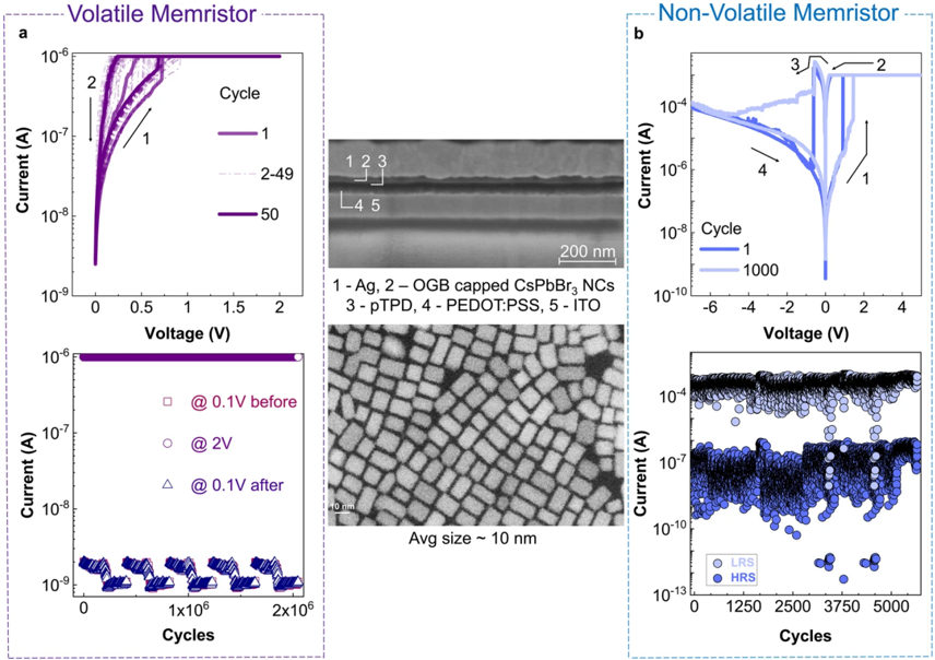
The image presents a comparison between volatile and non-volatile memristors, showcasing their current-voltage (I-V) characteristics and endurance (current vs. cycles). The left side (a) focuses on a volatile memristor, while the right side (b) focuses on a non-volatile memristor. A schematic diagram and a transmission electron microscopy (TEM) image are also included to provide structural context.
### Components/Axes
**Volatile Memristor (a):**
* **Top Chart:** I-V curves. X-axis: Voltage (V) from 0 to 1.25. Y-axis: Current (A) on a logarithmic scale from 10^-8 to 10^-6.
* **Bottom Chart:** Current vs. Cycles. X-axis: Cycles from 0 to 2x10^6. Y-axis: Current (A) on a logarithmic scale from 10^-9 to 10^-6.
* **Legend (Top Chart):**
* 1: Cycle 1 (Dark Purple)
* 2-49: Intermediate Cycles (Light Purple)
* 50: Cycle 50 (Red)
* **Legend (Bottom Chart):**
* @ 0.1V before (Purple Squares)
* @ 2V (Light Blue Circles)
* @ 0.1V after (Light Purple Triangles)
**Non-Volatile Memristor (b):**
* **Top Chart:** I-V curves. X-axis: Voltage (V) from -6 to 4. Y-axis: Current (A) on a logarithmic scale from 10^-10 to 10^-4.
* **Bottom Chart:** Current vs. Cycles. X-axis: Cycles from 0 to 5000. Y-axis: Current (A) on a logarithmic scale from 10^-13 to 10^-7.
* **Legend (Top Chart):**
* 1: Cycle 1 (Dark Blue)
* 2: Cycle 2 (Light Blue)
* 3: Cycle 3 (Dark Blue)
* 4: Cycle 4 (Light Blue)
* **Legend (Bottom Chart):**
* LRS: Low Resistance State (Blue Circles)
* HRS: High Resistance State (Orange Circles)
**Schematic Diagram (Center):**
* Labeled layers: 1-Ag, 2-OGB capped CsPbBr3 NCs, 3-ptPD, 4-PEDOT:PSS, 5-ITO. Scale bar: 200 nm.
**TEM Image (Center):**
* Shows a lattice structure. Average size ~ 10 nm.
### Detailed Analysis or Content Details
**Volatile Memristor (a):**
* **Top Chart:** The I-V curves show a hysteresis loop that diminishes with increasing cycles. Cycle 1 (dark purple) exhibits a clear hysteresis. As the cycle number increases (light purple), the hysteresis loop becomes smaller, and by cycle 50 (red), the loop is significantly reduced.
* **Bottom Chart:** The current at 0.1V before cycling is approximately 5x10^-7 A. The current at 2V is approximately 2x10^-6 A. After cycling at 0.1V, the current drops to approximately 2x10^-8 A. The current remains relatively stable over 2 million cycles, with some fluctuations.
**Non-Volatile Memristor (b):**
* **Top Chart:** The I-V curves show a more pronounced hysteresis loop that persists across multiple cycles. Cycle 1 (dark blue) and Cycle 2 (light blue) show a clear switching behavior. The curves exhibit a pinched hysteresis loop.
* **Bottom Chart:** The device alternates between Low Resistance State (LRS) and High Resistance State (HRS). The LRS current is approximately 5x10^-7 A, while the HRS current is approximately 1x10^-11 A. The device shows stable switching between LRS and HRS for up to 5000 cycles.
**Schematic Diagram:**
* The diagram illustrates a layered structure of the memristor, with Ag, CsPbBr3 nanocrystals, ptPD, PEDOT:PSS, and ITO layers.
**TEM Image:**
* The TEM image reveals a lattice structure with an average size of approximately 10 nm.
### Key Observations
* The volatile memristor exhibits a diminishing hysteresis loop with increasing cycles, indicating a loss of memory.
* The non-volatile memristor maintains a stable hysteresis loop and switching behavior between LRS and HRS, demonstrating its non-volatile nature.
* The schematic diagram and TEM image provide insights into the device's structure and nanoscale features.
* The current difference between LRS and HRS in the non-volatile memristor is significant, indicating a clear on/off ratio.
### Interpretation
The data demonstrates a clear distinction between volatile and non-volatile memristor behavior. The volatile memristor's I-V characteristics change significantly with cycling, losing its initial hysteresis and thus its memory capability. This suggests that the resistance state is not retained after repeated switching. In contrast, the non-volatile memristor exhibits stable switching between LRS and HRS, indicating a persistent memory effect. The layered structure shown in the schematic diagram and the nanoscale features observed in the TEM image likely contribute to the observed memristive behavior. The CsPbBr3 nanocrystals are likely the active material responsible for the resistance switching. The difference in performance between the two memristor types highlights the importance of material selection and device architecture in achieving stable non-volatile memory. The large difference in current between LRS and HRS in the non-volatile memristor suggests a high on/off ratio, which is crucial for practical applications.