## Composite Figure: Particle Dynamics in a Channel
### Overview
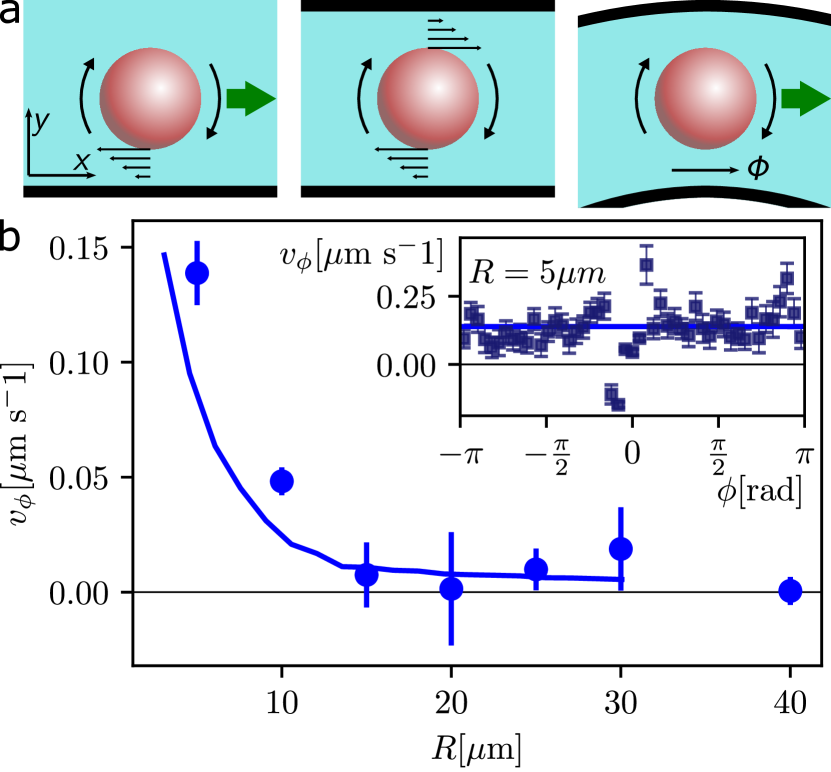
The image is a two-part scientific figure illustrating the motion of a spherical particle within a fluid-filled channel. Part (a) is a schematic diagram showing three different scenarios of particle rotation and translation. Part (b) is a quantitative data plot showing the relationship between the particle's rotational velocity and its radius, with an inset showing velocity as a function of phase angle.
### Components/Axes
**Part (a) - Schematic Diagram:**
* **Coordinate System:** A standard Cartesian coordinate system is shown in the bottom-left of the first panel, with the x-axis pointing right and the y-axis pointing up.
* **Panels:** Three panels depict a pink sphere (particle) inside a light blue channel bounded by black walls.
* **Left Panel:** The particle rotates clockwise (curved black arrows) and translates to the right (green arrow). Horizontal black lines below the particle indicate a shear flow profile.
* **Middle Panel:** The particle rotates counter-clockwise (curved black arrows) and translates to the right (green arrow). Horizontal black lines above and below the particle indicate a different shear flow profile.
* **Right Panel:** The particle rotates clockwise (curved black arrows) and translates to the right (green arrow). The channel walls are curved. A horizontal black arrow labeled with the Greek letter phi (φ) points to the right, indicating a phase or angular coordinate.
**Part (b) - Data Plot:**
* **Main Plot Axes:**
* **X-axis:** Labeled `R [μm]` (Radius in micrometers). Major tick marks at 10, 20, 30, 40.
* **Y-axis:** Labeled `v_φ [μm s⁻¹]` (Rotational velocity in micrometers per second). Major tick marks at 0.00, 0.05, 0.10, 0.15.
* **Data Series:** A single data series represented by blue circular markers with vertical error bars. A solid blue line connects the markers, showing a fitted trend.
* **Inset Plot:** Located in the top-right quadrant of the main plot.
* **Title/Label:** `R = 5 μm` (indicating data for a particle of 5 micrometer radius).
* **X-axis:** Labeled `φ [rad]` (Phase angle in radians). Major tick marks at -π, -π/2, 0, π/2, π.
* **Y-axis:** Shares the same label and scale as the main plot's y-axis (`v_φ [μm s⁻¹]`). Major tick marks at 0.00, 0.25.
* **Data:** Blue square markers with error bars, scattered around a horizontal blue line at approximately v_φ = 0.12 μm s⁻¹.
### Detailed Analysis
**Main Plot (v_φ vs. R):**
* **Trend Verification:** The data shows a clear, steeply decreasing trend. As the radius `R` increases, the rotational velocity `v_φ` decreases rapidly, approaching zero for larger radii.
* **Data Points (Approximate):**
* At R ≈ 5 μm, v_φ ≈ 0.14 μm s⁻¹ (highest point).
* At R ≈ 10 μm, v_φ ≈ 0.05 μm s⁻¹.
* At R ≈ 15 μm, v_φ ≈ 0.01 μm s⁻¹.
* At R ≈ 20 μm, v_φ ≈ 0.00 μm s⁻¹ (within error bars).
* At R ≈ 25 μm, v_φ ≈ 0.01 μm s⁻¹.
* At R ≈ 30 μm, v_φ ≈ 0.02 μm s⁻¹.
* At R ≈ 40 μm, v_φ ≈ 0.00 μm s⁻¹.
* The solid blue line suggests an inverse relationship, possibly a power-law decay (e.g., v_φ ∝ 1/R or 1/R²).
**Inset Plot (v_φ vs. φ for R=5μm):**
* **Trend Verification:** The data points fluctuate around a constant positive value. There is no strong systematic trend with phase angle φ.
* **Data Distribution:** The rotational velocity `v_φ` for the 5 μm particle is consistently positive, centered around a mean value of approximately 0.12 μm s⁻¹ (indicated by the horizontal blue line). The scatter and error bars show the variability of the measurement across different phase angles from -π to π radians.
### Key Observations
1. **Strong Size Dependence:** The rotational velocity `v_φ` is highly sensitive to particle size `R`, dropping dramatically as the particle gets larger.
2. **Asymptotic Behavior:** For particles with R ≥ 15 μm, the rotational velocity becomes very small, consistent with zero within the measurement uncertainty.
3. **Phase Independence (for small R):** For the smallest measured particle (R=5 μm), the rotational velocity does not show a strong dependence on the phase angle φ, suggesting its rotation is steady relative to the channel phase.
4. **Schematic Context:** The diagrams in (a) suggest the rotation and translation are coupled and influenced by the channel geometry (straight vs. curved walls) and the local fluid shear profile.
### Interpretation
This figure investigates the dynamics of a particle (likely a vesicle or capsule) flowing through a microfluidic channel. The key finding is that **smaller particles rotate much faster** than larger ones under the same flow conditions. This is a classic signature of **tank-treading motion**, where the particle's membrane rotates while its shape remains steady, with the rotation rate inversely related to particle size.
The schematic in (a) provides the physical context: the particle's motion (translation and rotation) is driven by the shear flow in the channel. The curved walls in the rightmost panel and the phase variable φ suggest the study may involve channels with periodic or curved geometries, where the particle's orientation (phase) could be important.
The data in (b) quantitatively confirms the size-dependent rotation. The inset for R=5 μm shows that while the rotation is fast, it is relatively constant regardless of the particle's orientation (phase) within the channel. This implies that for small particles, the tank-treading frequency is set primarily by the global shear rate and particle size, not by its instantaneous position or orientation in a curved channel. The near-zero rotation for large particles (R > 15 μm) suggests a transition to a different motion regime, such as tumbling or steady orientation, where rotational velocity is minimal.