## Diagram: Torque Balance on a Lever
### Overview
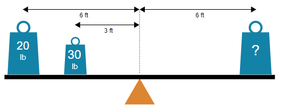
The image is a technical diagram illustrating the principle of torque equilibrium on a lever (seesaw). It depicts a balanced lever with known weights and distances on the left side and an unknown weight on the right side, posing a problem to solve for the unknown mass.
### Components/Axes
* **Main Structure:** A horizontal black bar representing a lever or beam.
* **Fulcrum:** An orange triangle positioned at the exact center of the lever, serving as the pivot point.
* **Weights:** Three blue, trapezoidal weight icons with circular handles on top.
* **Left Side (Two Weights):**
* A larger weight labeled **"20 lb"**.
* A smaller weight labeled **"30 lb"**.
* **Right Side (One Weight):**
* A larger weight labeled with a **"?"** (question mark), indicating an unknown value.
* **Distance Markers:** Black double-headed arrows with text labels indicating horizontal distances from the central fulcrum.
* An arrow from the fulcrum to the center of the **20 lb** weight is labeled **"6 ft"**.
* An arrow from the fulcrum to the center of the **30 lb** weight is labeled **"3 ft"**.
* An arrow from the fulcrum to the center of the **"?"** weight is labeled **"6 ft"**.
* **Language:** All text in the diagram is in **English**.
### Detailed Analysis
The diagram sets up a classic physics problem involving rotational equilibrium (sum of torques = 0). The lever is shown in a balanced, horizontal state.
**Left Side Torques (Counter-Clockwise):**
1. **Weight 1:** 20 lb at a distance of 6 ft from the fulcrum.
* Torque = Force × Distance = 20 lb × 6 ft = **120 lb-ft**.
2. **Weight 2:** 30 lb at a distance of 3 ft from the fulcrum.
* Torque = 30 lb × 3 ft = **90 lb-ft**.
* **Total Left Torque:** 120 lb-ft + 90 lb-ft = **210 lb-ft**.
**Right Side Torque (Clockwise):**
1. **Unknown Weight (?):** Let's call it *W* lb, at a distance of 6 ft from the fulcrum.
* Torque = *W* lb × 6 ft = **6*W* lb-ft**.
**Equilibrium Condition:** For the lever to be balanced, the total counter-clockwise torque must equal the total clockwise torque.
* 210 lb-ft = 6*W* lb-ft
* Solving for *W*: *W* = 210 / 6 = **35 lb**.
### Key Observations
* The diagram is spatially precise. The fulcrum is centered, and the distance markers clearly originate from the central dotted vertical line aligned with the fulcrum's apex.
* The visual placement of the weights corresponds to their labeled distances. The 30 lb weight is visibly closer to the fulcrum than the 20 lb weight, matching the 3 ft vs. 6 ft labels.
* The unknown weight on the right is placed at the same distance (6 ft) as the 20 lb weight on the left, but the system is balanced, implying it must be heavier than 20 lb to counteract the combined torque from the left side.
* The color coding is consistent: all weights are the same shade of blue, and the fulcrum is a distinct orange.
### Interpretation
This diagram is an educational tool demonstrating the **principle of moments** or **lever equilibrium**. It visually communicates that balance depends not just on weight (force), but on the product of weight and its distance from the pivot (torque).
The data suggests that to balance a system, a single weight on one side must produce a torque equal to the sum of all torques on the opposite side. The specific solution (35 lb) is a direct mathematical consequence of the given values. The "question mark" transforms the diagram from a mere illustration into an interactive problem, prompting the viewer to apply the formula: **Clockwise Torque = Counter-Clockwise Torque**.
There are no anomalies; the diagram is a clean, idealized representation of a fundamental physics concept. Its purpose is to teach or test understanding of rotational mechanics.