## Block Diagram: Processor/System-on-Chip (SoC) Architecture
### Overview
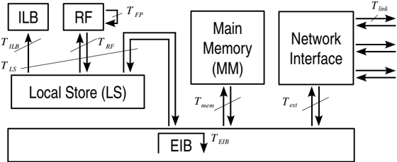
The image is a technical block diagram illustrating the high-level architecture and data/control flow of a processing system, likely a specialized processor or system-on-chip (SoC). It shows the interconnection between core computational units, memory hierarchy, and external interfaces via a central bus.
### Components/Axes
The diagram consists of several labeled rectangular blocks representing functional units, connected by arrows indicating data or control flow. Timing or latency parameters are labeled alongside these connections.
**Main Components (Blocks):**
1. **ILB** (Top-left)
2. **RF** (Top-left, to the right of ILB)
3. **Local Store (LS)** (Center-left, below ILB and RF)
4. **Main Memory (MM)** (Center)
5. **Network Interface** (Center-right)
6. **EIB** (Bottom, spanning the width of the diagram)
**Connections and Timing Labels:**
* **ILB to LS:** A single upward arrow labeled `T_ILB`.
* **LS to ILB:** A single downward arrow labeled `T_LS`.
* **RF to LS:** A double-headed arrow (bidirectional) labeled `T_RF`.
* **RF to MM:** A double-headed arrow (bidirectional) labeled `T_FP`.
* **LS to EIB:** A thick, downward-pointing arrow (indicating a bus or wide data path).
* **MM to EIB:** A double-headed arrow labeled `T_mem`.
* **Network Interface to EIB:** A double-headed arrow labeled `T_ext`.
* **EIB Internal:** A downward arrow within the EIB block labeled `T_EIB`.
* **Network Interface External:** Multiple horizontal arrows pointing to/from the right edge of the diagram, labeled `T_link`.
### Detailed Analysis
**Spatial Layout and Flow:**
* **Top-Left Region:** Contains the **ILB** and **RF** units, which are closely coupled with the **Local Store (LS)**. This suggests a local, high-speed processing cluster.
* **Central Region:** Houses the **Main Memory (MM)** and **Network Interface**, acting as bridges to larger storage and external systems.
* **Bottom Region:** The **EIB** (likely standing for *External Interface Bus* or *Element Interconnect Bus*) serves as the central communication backbone, connecting all major components.
* **Data Flow:** The arrows depict a clear hierarchy. The ILB/RF/LS cluster processes data locally. For larger datasets or external communication, data moves via the EIB to/from the Main Memory or Network Interface.
**Component Relationships:**
* The **Local Store (LS)** acts as a scratchpad or cache, directly serving the ILB and RF.
* The **RF** (Register File) has a direct, bidirectional link to **Main Memory (MM)**, labeled `T_FP`. This could indicate a path for floating-point operations or direct memory access (DMA) by the register file.
* The **Network Interface** manages all external communication (`T_link`), funneling data through the EIB (`T_ext`) to the rest of the system.
### Key Observations
1. **Centralized Interconnect:** The EIB is the single point of connection for the Local Store, Main Memory, and Network Interface, making it a critical potential bottleneck.
2. **Asymmetric Local Access:** The ILB has a dedicated, likely read-only, path from the LS (`T_ILB`), while the RF has a full bidirectional path (`T_RF`). This suggests the ILB might be an instruction buffer or loader.
3. **Direct RF-Memory Path:** The `T_FP` connection between RF and MM is notable, bypassing the LS and EIB for certain operations, which could be optimized for performance.
4. **Timing-Centric Design:** Every major data path is annotated with a timing parameter (`T_...`), emphasizing that latency and synchronization are critical design considerations for this architecture.
### Interpretation
This diagram represents a **performance-optimized, memory-centric computing architecture**. The design prioritizes low-latency access for local processing (ILB/RF/LS cluster) while providing scalable paths to larger memory and external networks.
* **What it demonstrates:** The system is built for tasks requiring high-bandwidth, low-latency local computation (e.g., signal processing, scientific computing) with the ability to handle large datasets (via MM) and communicate with other systems (via Network Interface).
* **Relationships:** The hierarchy is clear: Fast, local resources (LS) feed specialized processors (ILB, RF). The EIB orchestrates data movement between this fast layer and the slower, larger-capacity or external layers (MM, Network).
* **Notable Design Choice:** The direct `T_FP` link between the Register File and Main Memory is a significant architectural feature. It implies the system may support operations that stream data directly from main memory into registers for processing, minimizing intermediate storage overhead. This is common in high-performance computing (HPC) or graphics processing unit (GPU) designs.
* **Potential Bottleneck:** The EIB's role as the sole conduit for MM and Network traffic means its bandwidth and latency (`T_EIB`) will fundamentally limit the system's overall throughput for non-local operations.