## Diagram: Structural Equivalence Representation
### Overview
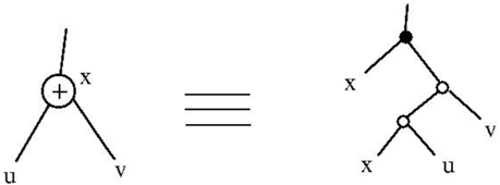
The image depicts two equivalent diagrammatic representations connected by a triple horizontal line (≡), indicating structural isomorphism. The left diagram shows a central node labeled "+" with three branches labeled "u," "v," and "x." The right diagram illustrates a tree-like structure with nodes labeled "x," "u," "v," and a blackened node, suggesting hierarchical relationships.
### Components/Axes
- **Left Diagram**:
- Central node: "+" (likely a root or aggregation point).
- Branches: "u," "v," "x" (direct connections to the central node).
- **Right Diagram**:
- Root node: Blackened node (no explicit label).
- Branches:
- Direct child: "x" (connected to root).
- Sub-branches from "x": "u" and "v" (nested hierarchy).
- **Equivalence Symbol**: Triple horizontal line (≡) between diagrams, denoting equivalence in structure or function.
### Detailed Analysis
- **Left Diagram**:
- The "+" node acts as a hub with equal-weight connections to "u," "v," and "x."
- No explicit hierarchy; all branches are direct and symmetric.
- **Right Diagram**:
- Hierarchical structure: Root → "x" → ("u," "v").
- The blackened node implies a distinct role (e.g., root, primary node, or special identifier).
- **Equivalence Implications**:
- The diagrams represent the same logical structure but differ in visualization (star vs. tree).
- The blackened node in the right diagram may correspond to the "+" node in the left, acting as the root.
### Key Observations
1. **Symmetry vs. Hierarchy**: The left diagram emphasizes symmetry, while the right enforces a parent-child relationship.
2. **Node Roles**: The "+" node (left) and blackened node (right) likely represent the same entity in different contexts.
3. **Label Consistency**: "u" and "v" appear in both diagrams, suggesting they are terminal or leaf nodes.
### Interpretation
This equivalence likely illustrates a concept in graph theory, data structures, or system design where different visualizations represent identical underlying relationships. The blackened node in the right diagram may denote a root or primary node, while the "+" in the left diagram abstracts this role. The equivalence symbol (≡) underscores that the structural relationships (e.g., connections between "u," "v," and "x") remain invariant despite differing representations. This could apply to scenarios like network topologies, decision trees, or organizational charts where hierarchical and flat views coexist.