## Flowchart Diagram: Logical Implication System
### Overview
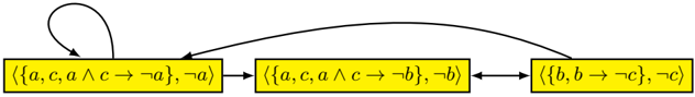
The diagram depicts a cyclic logical system with three interconnected states represented by yellow rectangles. Each state contains a set of logical propositions and their negations, connected by directional arrows indicating transformation or dependency relationships. A self-loop exists on the first state.
### Components/Axes
1. **Rectangles (States)**:
- **State 1**: ⟨{a, c, a ∧ c → ¬a}, ¬a⟩
- Contains propositions: `a`, `c`, and implication `a ∧ c → ¬a`
- Negation: `¬a`
- **State 2**: ⟨{a, c, a ∧ c → ¬b}, ¬b⟩
- Contains propositions: `a`, `c`, and implication `a ∧ c → ¬b`
- Negation: `¬b`
- **State 3**: ⟨{b, b → ¬c}, ¬c⟩
- Contains propositions: `b` and implication `b → ¬c`
- Negation: `¬c`
2. **Arrows (Flow/Dependencies)**:
- **Arrow 1**: From State 1 → State 2 (solid line)
- **Arrow 2**: From State 2 → State 3 (solid line)
- **Arrow 3**: From State 3 → State 1 (solid line)
- **Self-loop**: On State 1 (dashed line)
### Detailed Analysis
- **Logical Structure**:
Each state represents a logical environment with embedded propositions and their negations. The implications (`→`) and conjunctions (`∧`) suggest conditional dependencies between variables (`a`, `b`, `c`).
- State 1: If `a` and `c` are true, then `¬a` must hold (contradiction unless `a` or `c` is false).
- State 2: If `a` and `c` are true, then `¬b` must hold.
- State 3: If `b` is true, then `¬c` must hold.
- **Flow Dynamics**:
The cyclic flow (State 1 → State 2 → State 3 → State 1) implies a sequential transformation of logical constraints. The self-loop on State 1 suggests iterative refinement or stabilization of the `a ∧ c → ¬a` rule.
### Key Observations
1. **Contradiction in State 1**: The implication `a ∧ c → ¬a` creates a paradox unless `a` or `c` is false.
2. **Dependency Chain**:
- State 1’s `¬a` propagates to State 2, where `a ∧ c → ¬b` may enforce `¬b` if `a` and `c` are true.
- State 2’s `¬b` influences State 3, where `b → ¬c` would require `¬c` if `b` is true.
3. **Cyclic Dependency**: The loop from State 3 back to State 1 introduces a feedback mechanism, potentially creating a closed logical system.
### Interpretation
This diagram models a **non-monotonic logical system** where propositions and their negations coexist, governed by conditional rules. The cyclic flow suggests:
- **Iterative Refinement**: The self-loop on State 1 may represent repeated evaluation of `a ∧ c → ¬a` to resolve contradictions.
- **Constraint Propagation**: Changes in one state (e.g., `¬a`) ripple through the system, enforcing dependencies in subsequent states.
- **Paradox Avoidance**: The system appears designed to prevent contradictions by dynamically adjusting negations (e.g., `¬a`, `¬b`, `¬c`).
The structure resembles a **formal proof system** or **automated theorem prover**, where logical rules are applied iteratively to derive conclusions while avoiding inconsistencies. The absence of numerical data implies a focus on symbolic reasoning rather than quantitative analysis.