## Diagram: Network Topology and Flow Logic
### Overview
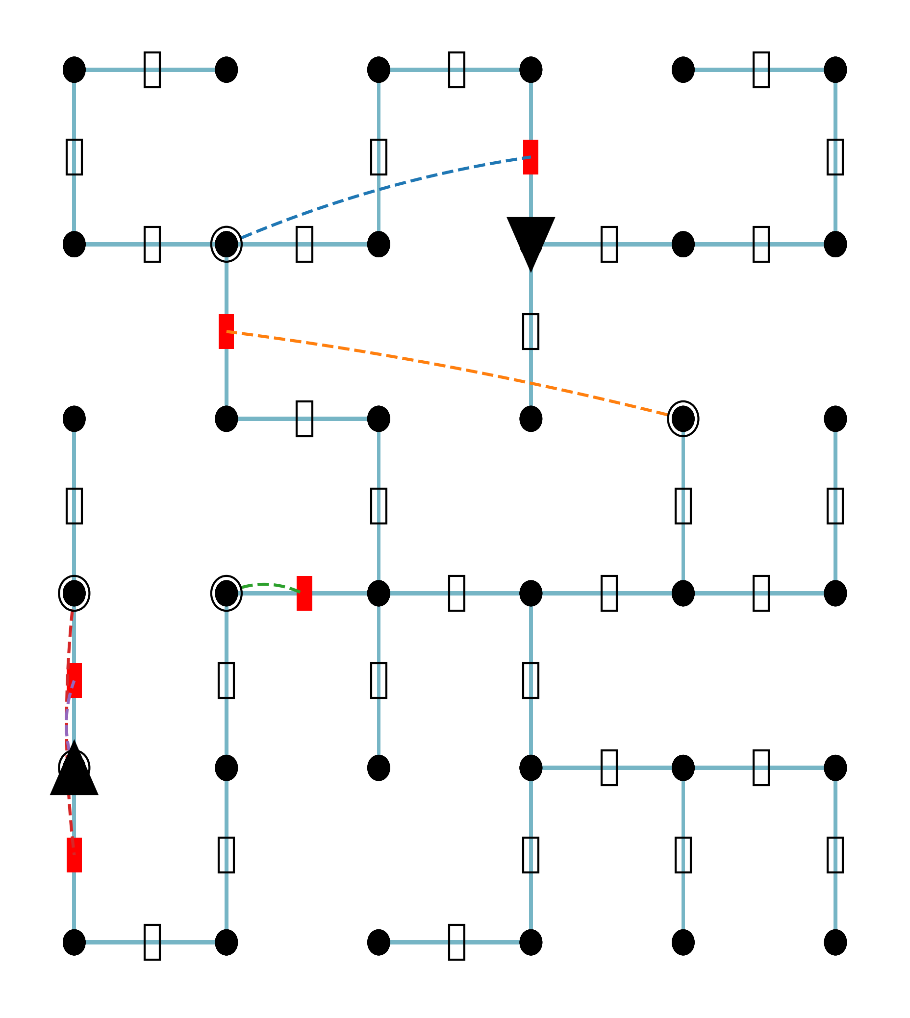
The image displays a 5x5 grid-based network diagram. It consists of nodes connected by solid light-blue lines and dashed colored lines. The diagram appears to represent a flow network, circuit, or routing puzzle where specific nodes act as hubs or directional gates, and dashed lines represent non-standard or "jump" connections between nodes.
### Components/Axes
* **Grid Structure:** A 5x5 matrix of nodes.
* **Nodes:**
* **Standard Nodes:** Solid black circles.
* **Hub Nodes:** Double-ringed black circles (located at (2,2), (3,5), (4,1), (4,2)).
* **Directional Nodes:** Black triangles (pointing down at (2,4), pointing up at (5,1)).
* **Edges:**
* **Standard Edges:** Solid light-blue lines connecting adjacent nodes horizontally and vertically. Each segment contains a small white rectangle (likely representing a resistor, gate, or standard path segment).
* **Special Edges:** Dashed lines connecting non-adjacent nodes. Each dashed line features a red rectangle (likely representing a switch, override, or high-cost path).
* **Coordinate System (for reference):**
* Rows 1-5 (top to bottom).
* Columns 1-5 (left to right).
### Detailed Analysis
The diagram features four distinct "special" connections.