TECHNICAL ASSET FINGERPRINT
3b8d835bbcaca54f5cc1c8aa
Click to view fullscreen
Press ESC or click to close
FOUND IN PAPERS
EXPERT: gemini-2.5-flash-lite-free VERSION 1
RUNTIME: google-free/gemini-2.5-flash-lite
INTEL_VERIFIED
## Diagram: Transformer Quantization Workflow for Computer Vision and NLP
### Overview
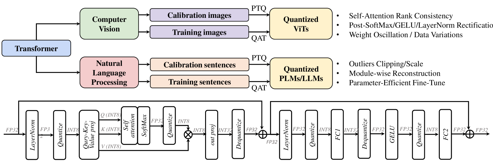
This diagram illustrates a generalized workflow for applying quantization techniques to Transformer models in both Computer Vision (CV) and Natural Language Processing (NLP) domains. It shows how different types of input data (images and sentences) are processed through a Transformer architecture, leading to quantized models. The diagram also depicts two distinct, detailed sub-workflows representing the internal processing of a quantized Transformer block, likely for either CV or NLP tasks, showing the flow of data through various operations like normalization, quantization, attention mechanisms, and feed-forward layers.
### Components/Axes
The diagram is structured into three main sections:
**Top Section: High-Level Workflow**
* **Input Branches:**
* **Transformer (Blue Box):** A central component from which two main processing branches originate.
* **Computer Vision (Green Box):** Represents the application domain for image data.
* **Natural Language Processing (Pink Box):** Represents the application domain for text data.
* **Data Types:**
* **Calibration images (Purple Box):** Input data for CV calibration.
* **Training images (Purple Box):** Input data for CV training.
* **Calibration sentences (Orange Box):** Input data for NLP calibration.
* **Training sentences (Orange Box):** Input data for NLP training.
* **Quantization Methods:**
* **PTQ (Post-Training Quantization):** A label indicating a quantization method applied to calibration data.
* **QAT (Quantization-Aware Training):** A label indicating a quantization method applied to training data.
* **Output Models:**
* **Quantized ViTs (Yellow Box):** Represents quantized Vision Transformers.
* **Quantized PLMs/LLMs (Yellow Box):** Represents quantized Pre-trained Language Models / Large Language Models.
* **Associated Techniques/Challenges:**
* **For Quantized ViTs:**
* Self-Attention Rank Consistency
* Post-SoftMax/GELU/LayerNorm Rectification
* Weight Oscillation / Data Variations
* **For Quantized PLMs/LLMs:**
* Outliers Clipping/Scale
* Module-wise Reconstruction
* Parameter-Efficient Fine-Tune
**Bottom Section: Detailed Quantized Transformer Block (Left)**
This section depicts a detailed view of a Transformer block, likely for processing input features.
* **Input Data Type:**
* **FP32:** Indicates input data is in 32-bit floating-point format.
* **Sequential Operations (Rectangular Boxes):**
* **LayerNorm:** Layer Normalization.
* **Quantize:** Quantization operation.
* **Q (INT8), K (INT8), V (INT8):** Query, Key, and Value projections, with data quantized to 8-bit integers.
* **Self attention:** Self-attention mechanism.
* **SoftMax:** Softmax activation function.
* **FP32:** Intermediate output in 32-bit floating-point format.
* **Quantize:** Another quantization operation.
* **out proj:** Output projection.
* **INT8:** Output data quantized to 8-bit integers.
* **INT32:** Intermediate data in 32-bit integers.
* **Dequantize:** Dequantization operation.
* **FP32:** Output data in 32-bit floating-point format.
* **Operations (Symbols):**
* **⊕ (Circle with Plus):** Element-wise addition (residual connection).
**Bottom Section: Detailed Quantized Transformer Block (Right)**
This section depicts another detailed view of a Transformer block, likely a subsequent layer or a different type of block.
* **Input Data Type:**
* **FP32:** Indicates input data is in 32-bit floating-point format.
* **Sequential Operations (Rectangular Boxes):**
* **LayerNorm:** Layer Normalization.
* **Quantize:** Quantization operation.
* **INT8:** Output data quantized to 8-bit integers.
* **FC1:** First Feed-Forward layer (likely a linear transformation).
* **INT32:** Intermediate data in 32-bit integers.
* **Dequantize:** Dequantization operation.
* **FP32:** Output data in 32-bit floating-point format.
* **GELU:** Gaussian Error Linear Unit activation function.
* **Quantize:** Another quantization operation.
* **INT8:** Output data quantized to 8-bit integers.
* **FC2:** Second Feed-Forward layer (likely a linear transformation).
* **FP32:** Output data in 32-bit floating-point format.
* **Operations (Symbols):**
* **⊕ (Circle with Plus):** Element-wise addition (residual connection).
* **Loop Arrow:** Indicates a residual connection from a previous layer (or the input) to the output of the FC2 layer before the final addition.
### Detailed Analysis or Content Details
**Top Section:**
* The diagram shows that a "Transformer" architecture can be applied to both "Computer Vision" and "Natural Language Processing".
* For CV, "Calibration images" are processed via "PTQ" to yield "Quantized ViTs". "Training images" are processed via "QAT" to yield "Quantized ViTs".
* For NLP, "Calibration sentences" are processed via "PTQ" to yield "Quantized PLMs/LLMs". "Training sentences" are processed via "QAT" to yield "Quantized PLMs/LLMs".
* The associated bullet points for "Quantized ViTs" highlight potential issues like "Self-Attention Rank Consistency", "Post-SoftMax/GELU/LayerNorm Rectification", and "Weight Oscillation / Data Variations".
* The associated bullet points for "Quantized PLMs/LLMs" highlight potential issues like "Outliers Clipping/Scale", "Module-wise Reconstruction", and "Parameter-Efficient Fine-Tune".
**Bottom Section (Left Block):**
* The flow starts with **FP32** data.
* It passes through **LayerNorm**, then is **Quantized**. The diagram indicates a transition to INT8 for Q, K, V.
* This is followed by a projection into **Query (INT8)**, **Key (INT8)**, and **Value (INT8)**.
* These are fed into a **Self attention** mechanism, followed by **SoftMax**.
* The output of SoftMax is **FP32**.
* This FP32 output is then **Quantized** to **INT8**.
* This INT8 output is then processed by an **out proj** layer, resulting in **INT8** data.
* This INT8 data is then converted to **INT32** and subsequently **Dequantized** back to **FP32**.
* Finally, this FP32 output is added element-wise (residual connection) with another FP32 input (indicated by the ⊕ symbol).
**Bottom Section (Right Block):**
* The flow starts with **FP32** data.
* It passes through **LayerNorm**, then is **Quantized** to **INT8**.
* This INT8 data is processed by **FC1**, resulting in **INT32** data.
* This INT32 data is then **Dequantized** to **FP32**.
* This FP32 data passes through a **GELU** activation.
* The output of GELU is then **Quantized** to **INT8**.
* This INT8 data is processed by **FC2**, resulting in **FP32** data.
* Finally, this FP32 output is added element-wise (residual connection) with another FP32 input (indicated by the ⊕ symbol). A loop arrow indicates this residual connection originates from a point earlier in the network, likely before the LayerNorm in this block.
### Key Observations
* The diagram clearly distinguishes between Post-Training Quantization (PTQ) and Quantization-Aware Training (QAT), with PTQ using calibration data and QAT using training data.
* Both CV (ViTs) and NLP (PLMs/LLMs) models are shown to undergo similar quantization workflows.
* The detailed sub-diagrams illustrate a common pattern in Transformer blocks: normalization, quantization, attention/projection, activation, and residual connections.
* There's a significant amount of quantization and dequantization happening within the detailed blocks, suggesting a focus on mixed-precision or aggressive quantization.
* The presence of INT8 and INT32 data types indicates the use of low-precision integer representations for computational efficiency.
* The residual connections (⊕) are crucial for maintaining model performance during quantization, a standard practice in deep learning architectures.
* The specific challenges listed for ViTs and PLMs/LLMs suggest areas of active research and potential pitfalls in quantizing these models.
### Interpretation
This diagram outlines a generalized methodology for quantizing Transformer models for both computer vision and natural language processing tasks. It highlights that the choice of quantization method (PTQ vs. QAT) depends on the availability of calibration or training data, respectively. The subsequent detailed sub-diagrams provide a glimpse into the internal mechanics of how these quantized models operate, showcasing the interplay between various operations like normalization, attention, feed-forward layers, and crucially, the repeated quantization and dequantization steps.
The diagram suggests that achieving effective quantization for advanced models like Vision Transformers (ViTs) and Large Language Models (LLMs) involves addressing specific challenges. For ViTs, maintaining the integrity of the self-attention mechanism and mitigating issues like weight oscillation are key. For NLP models, handling outliers and employing module-wise reconstruction are important considerations. The emphasis on mixed precision (e.g., INT8, INT32, FP32) within the detailed blocks implies a strategy to balance computational efficiency with model accuracy. The residual connections are a fundamental architectural element that helps preserve information flow and gradients, which is particularly vital when reducing precision. Overall, the diagram serves as a conceptual blueprint for understanding the process and complexities of deploying quantized Transformer models in real-world applications.
DECODING INTELLIGENCE...