## Composite Technical Diagram: ReRAM Array Characterization
### Overview
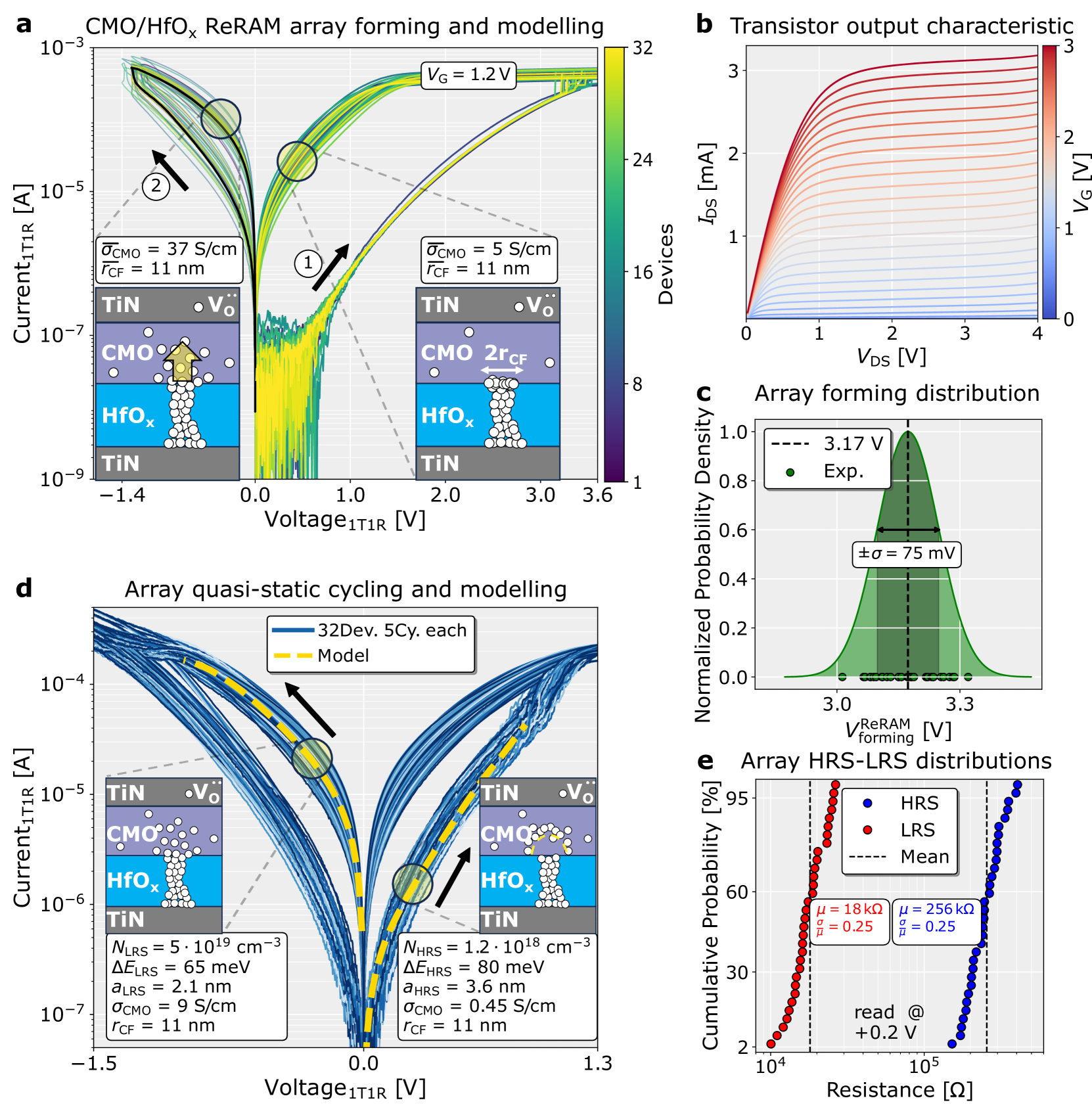
The image presents a multi-panel technical analysis of a CMOS/HfOₓ ReRAM array, combining experimental data, modeling, and device characterization. Panels a-e illustrate array forming behavior, transistor characteristics, statistical distributions, and operational states.
---
### Panel a: CMO/HfOₓ ReRAM Array Forming and Modelling
#### Components/Axes
- **Y-axis**: Current₁T1R [A] (log scale: 10⁻⁹ to 10⁻³)
- **X-axis**: Voltage₁T1R [V] (-1.4 to 3.6)
- **Legend**: Two curves with σ_CMO = 37 S/cm (green) and σ_CMO = 5 S/cm (blue), both with r_CF = 11 nm
- **Inset diagrams**: Cross-sectional views of TiN/CMO/HfOₓ/TiN layers with voltage polarity indicators
#### Detailed Analysis
1. **Forming Curves**:
- Two distinct forming curves show current increase during voltage sweep
- Higher σ_CMO (37 S/cm) exhibits steeper current rise (labeled "2" with arrow)
- Lower σ_CMO (5 S/cm) shows gradual transition (labeled "1" with arrow)
2. **Voltage Thresholds**:
- V_G = 1.2 V marked at upper right
- Current thresholds at 10⁻⁵ A and 10⁻⁷ A indicated
#### Key Observations
- Higher conductivity CMO layers enable faster forming transitions
- Both models predict similar final resistance states (r_CF = 11 nm)
---
### Panel b: Transistor Output Characteristic
#### Components/Axes
- **Y-axis**: I_DS [mA] (0 to 3)
- **X-axis**: V_DS [V] (0 to 4)
- **Color gradient**: V_G from 0 V (blue) to 3 V (red)
- **Legend**: Color bar on right with V_G scale
#### Detailed Analysis
- **I-V Curves**:
- All curves show saturation behavior
- Higher V_G (red) corresponds to higher saturation current
- Linear region slope increases with V_G
- **Key Trend**: V_G modulates channel conductivity through gate voltage
---
### Panel c: Array Forming Distribution
#### Components/Axes
- **X-axis**: V_ReRAM_forming [V] (2.8 to 3.4)
- **Y-axis**: Normalized Probability Density (0 to 1)
- **Legend**: Dashed line (theoretical) vs. dots (experimental)
- **Statistical markers**: Mean = 3.17 V, σ = 75 mV
#### Detailed Analysis
- **Distribution Shape**:
- Bell-shaped curve centered at 3.17 V
- Experimental data (dots) align with theoretical prediction
- ±σ range spans 2.995 V to 3.345 V
- **Key Insight**: Forming voltage follows Gaussian distribution with tight variance
---
### Panel d: Array Quasi-Static Cycling and Modelling
#### Components/Axes
- **Y-axis**: Current₁T1R [A] (10⁻⁷ to 10⁻⁴)
- **X-axis**: Voltage₁T1R [V] (-1.5 to 1.3)
- **Legend**: Blue (32 devices) vs. dashed yellow (model)
- **Inset parameters**:
- N_LRS = 5×10¹⁹ cm⁻³, ΔE_LRS = 65 meV
- N_HRS = 1.2×10¹⁸ cm⁻³, ΔE_HRS = 80 meV
#### Detailed Analysis
- **Cycling Behavior**:
- Experimental (blue) shows multi-state switching
- Model (yellow) predicts idealized switching thresholds
- Both show hysteresis loops with similar V_on/V_off
- **Key Difference**: Experimental data exhibits broader current distribution
---
### Panel e: Array HRS-LRS Distributions
#### Components/Axes
- **X-axis**: Resistance [Ω] (10⁴ to 10⁵)
- **Y-axis**: Cumulative Probability (%) (0 to 95)
- **Legend**: Blue dots (HRS) vs. red dots (LRS)
- **Statistical markers**: μ_HRS = 256 kΩ, μ_LRS = 18 kΩ; σ/μ = 0.25 for both
#### Detailed Analysis
- **State Separation**:
- HRS (blue) dominates high-resistance tail (>10⁵ Ω)
- LRS (red) occupies low-resistance region (<10⁴ Ω)
- Clear bimodal distribution with minimal overlap
- **Key Metric**: 95% probability threshold at 10⁵ Ω for HRS
---
### Interpretation
1. **Forming Mechanism**: Higher σ_CMO layers enable faster forming transitions, validated by steeper current rise in panel a
2. **Operational States**: Panel e confirms distinct HRS/LRS states with statistical separation, critical for binary logic applications
3. **Model Validation**: Panel d shows experimental data closely matches theoretical predictions, though real devices exhibit broader current distributions
4. **Voltage Control**: Panel b demonstrates V_G's role in modulating channel conductivity, essential for transistor operation
5. **Manufacturing Consistency**: Panel c's narrow forming voltage distribution (σ = 75 mV) suggests process control maturity
The data collectively demonstrates a mature ReRAM technology with well-defined forming characteristics, stable operational states, and effective voltage control mechanisms. Experimental results closely align with theoretical models, suggesting reliable device performance across multiple fabrication batches.