## Diagram: Neural Network Architecture
### Overview
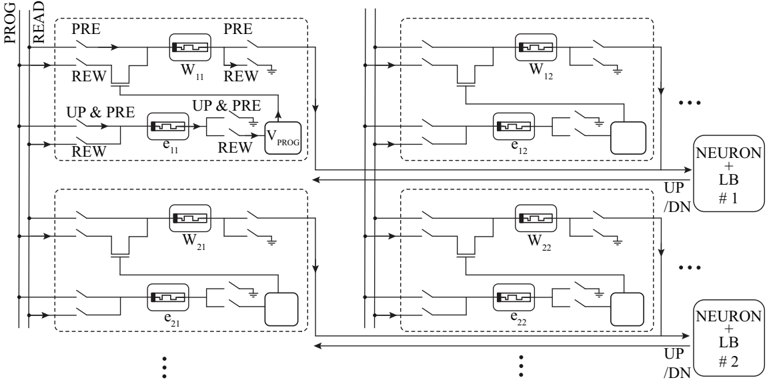
The image depicts a schematic diagram of a neural network architecture, likely a memory-based or neuromorphic computing system. It shows interconnected blocks representing neurons and associated logic gates, with signals labeled "PRE", "REW", "UP & PRE", "UP/DN", and "PROG". The diagram appears to illustrate the flow of signals during programming (PROG) and read operations (READ). The structure is repeated, suggesting a multi-layered or array-based implementation.
### Components/Axes
The diagram consists of repeating blocks, each representing a neuron and associated circuitry. Key labels include:
* **PROG/READ:** Input signal indicating programming or read mode. Located on the left vertical edge.
* **PRE:** Precharge signal.
* **REW:** Read/Write enable signal.
* **UP & PRE:** Combined Up and Precharge signal.
* **UP/DN:** Up/Down signal.
* **W<sub>ij</sub>:** Weighting element (likely a transistor or resistive element). Subscripts 'ij' denote the connection between neurons.
* **c<sub>ij</sub>:** Capacitive element (likely a capacitor). Subscripts 'ij' denote the connection between neurons.
* **NEURON + LB #1 & #2:** Labels indicating neuron blocks with local buffering.
* The diagram is structured in a grid-like fashion, with rows and columns of neuron blocks.
* Ground symbol (represented by a triangle pointing downwards) is present in multiple locations.
### Detailed Analysis or Content Details
The diagram shows a repeating pattern of neuron blocks. Let's analyze one block in detail:
1. **Input Signals:** The block receives signals "PRE", "REW", and "UP & PRE" from the left. "PROG" is also present.
2. **Weighting Element (W<sub>ij</sub>):** A transistor-like element labeled "W<sub>ij</sub>" is connected to the "PRE" signal. This likely represents a synaptic weight.
3. **Capacitive Element (c<sub>ij</sub>):** A capacitor-like element labeled "c<sub>ij</sub>" is connected to the "REW" signal. This likely stores charge representing the neuron's state.
4. **Logic Gates:** Logic gates (AND-like symbols) combine signals "UP" and "PRE" to control the flow of current.
5. **Output Signal:** The block outputs the "UP/DN" signal to the next neuron block.
6. **Repetition:** The pattern repeats horizontally and vertically, forming an array of neurons. The "..." notation indicates that the array continues beyond the visible portion of the diagram.
The diagram shows the following signal flow:
* **Programming (PROG):** The "PROG" signal likely controls the writing of information into the capacitive element "c<sub>ij</sub>" via the "REW" signal and weighting element "W<sub>ij</sub>".
* **Reading (READ):** During read mode, the "PRE" signal charges the capacitive element, and the "REW" signal reads the stored charge. The "UP/DN" signal represents the output of the neuron.
### Key Observations
* The diagram emphasizes the interplay between precharge, read/write, and up/down signals in controlling the neuron's behavior.
* The use of weighting elements (W<sub>ij</sub>) and capacitive elements (c<sub>ij</sub>) suggests a memory-based or analog computing approach.
* The repeating structure indicates a scalable architecture.
* The diagram does not provide specific numerical values for the components or signals. It is a conceptual representation of the architecture.
### Interpretation
The diagram illustrates a neural network architecture that leverages analog memory elements (capacitors) and weighted connections (transistors) to perform computations. The "PROG/READ" signal suggests a dynamic system where the network can be programmed with specific weights and then used for inference. The "UP/DN" signal likely represents the neuron's activation level.
The architecture appears to be designed for efficient energy consumption and scalability. The use of local buffering ("LB") suggests an attempt to reduce the impact of parasitic capacitances and improve signal integrity. The diagram highlights the fundamental building blocks of a neuromorphic computing system, where computation is performed using physical properties of the hardware rather than purely digital logic.
The diagram is a high-level representation and does not provide details about the specific implementation of the transistors, capacitors, or logic gates. It focuses on the overall signal flow and the key components of the architecture. The absence of numerical values suggests that the diagram is intended to convey the conceptual design rather than a precise engineering specification. The diagram is a conceptual illustration of a neural network architecture, likely for research or educational purposes.