## Diagram: LLM-Based Hardware Design Flow
### Overview
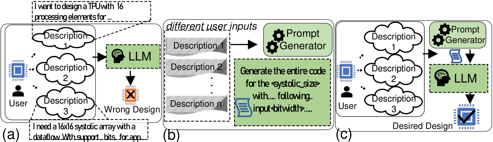
The image presents a diagram illustrating the evolution of a hardware design process using a Large Language Model (LLM). It contrasts an initial, potentially flawed design approach with a refined, desired design achieved through LLM and prompt engineering. The diagram is divided into three sections, labeled (a), (b), and (c), representing different stages of the design process.
### Components/Axes
* **Section (a): Initial Design (Wrong Design)**
* **User:** Represented by a human figure at the bottom-left.
* **Descriptions 1, 2, 3:** Cloud-shaped containers representing user input or design specifications.
* **LLM:** A green box labeled "LLM" with a brain icon, indicating the Large Language Model.
* **Wrong Design:** An orange box with an "X" mark, indicating a flawed design output.
* **Chip Icon:** A blue chip icon.
* **Section (b): Prompt Generation**
* **Different User Inputs:** Title of the section.
* **Descriptions 1, 2, n:** Gray boxes representing different user inputs.
* **Prompt Generator:** A green box with gear icons, indicating a prompt generation process.
* **Code Generation:** A green box containing text "Generate the entire code for the <systolic_size> with... following.. input <bitwidth>....".
* **Document Icon:** A blue document icon.
* **Section (c): Desired Design**
* **User:** Represented by a human figure at the bottom-left.
* **Descriptions 1, 2, 3:** Cloud-shaped containers representing user input or design specifications.
* **Prompt Generator:** A green box with gear icons, indicating a prompt generation process.
* **LLM:** A green box labeled "LLM" with a brain icon, indicating the Large Language Model.
* **Desired Design:** A blue chip icon with a checkmark, indicating a successful design output.
* **Chip Icon:** A blue chip icon.
### Detailed Analysis or ### Content Details
* **Section (a): Initial Design**
* The user provides descriptions (1, 2, 3) as input.
* These descriptions are fed into the LLM.
* The LLM generates a design, which is marked as "Wrong Design".
* A text box near the bottom-left states: "I need a 16x16 systolic array with a dataflow. With support...bits...for app..."
* **Section (b): Prompt Generation**
* The section is titled "different user inputs".
* Multiple descriptions (1, 2, ... n) are used as input.
* These descriptions are fed into a "Prompt Generator".
* The "Prompt Generator" creates code for the <systolic_size> with specific input <bitwidth>.
* **Section (c): Desired Design**
* The user provides descriptions (1, 2, 3) as input.
* These descriptions are fed into a "Prompt Generator".
* The output of the "Prompt Generator" is fed into the LLM.
* The LLM generates a design, which is marked as "Desired Design".
### Key Observations
* The diagram highlights the iterative nature of hardware design.
* The "Prompt Generator" plays a crucial role in refining the design process.
* The LLM is used in both the initial and final design stages, but with different inputs and outcomes.
* The initial design (a) is directly generated from user descriptions, while the desired design (c) is generated after prompt engineering.
### Interpretation
The diagram illustrates how an LLM can be used to design hardware, specifically a TPU (Tensor Processing Unit). The initial attempt (a) results in a "Wrong Design," likely due to insufficient or ambiguous input. By introducing a "Prompt Generator" (b), the user can refine the input and generate more specific instructions for the LLM. This refined input leads to a "Desired Design" (c), indicating that prompt engineering is essential for successful hardware design using LLMs. The diagram suggests that simply feeding user descriptions to an LLM is not enough; a prompt generation step is necessary to achieve the desired outcome. The mention of "systolic_size" and "bitwidth" indicates that the design involves specific hardware parameters that need to be carefully controlled through prompt engineering.