## Diagram: State Transformation and Verification Process
### Overview
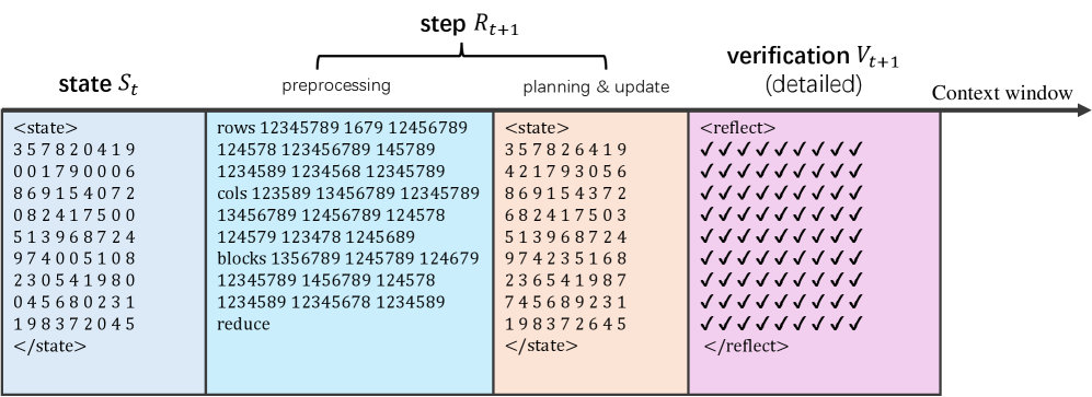
The image is a technical diagram illustrating a three-stage computational process for transforming and verifying a numerical state. It depicts a sequential flow from an initial state (`S_t`), through a processing step (`R_{t+1}`), to a verification stage (`V_{t+1}`), all contained within a conceptual "Context window." The diagram uses color-coded blocks and structured text to represent data and operations.
### Components/Axes
The diagram is organized horizontally into three main sections, followed by an arrow indicating the context window.
1. **Left Section: `state S_t`**
* **Label:** `state S_t` (top-left).
* **Content:** A 10x10 grid of single-digit integers enclosed within `<state>` and `</state>` tags.
* **Spatial Grounding:** This block is the leftmost element, with a light gray background.
2. **Middle Section: `step R_{t+1}`**
* **Label:** `step R_{t+1}` (centered above the section).
* **Sub-sections:** This section is divided into two colored blocks:
* **`preprocessing` (Light Blue Block):** Contains labeled lists of numbers.
* **`planning & update` (Light Orange Block):** Contains a transformed 10x10 state grid, also within `<state>` tags.
3. **Right Section: `verification V_{t+1}`**
* **Label:** `verification V_{t+1} (detailed)` (top-right of the block).
* **Content:** A 10x10 grid of checkmark symbols (`✓`) enclosed within `<reflect>` and `</reflect>` tags.
* **Spatial Grounding:** This block has a light purple background and is the rightmost colored section.
4. **Context Window Arrow**
* **Label:** `Context window` (above the arrow).
* **Description:** A black arrow originates from the right edge of the verification block and points to the right, extending beyond the diagram's main content.
### Detailed Analysis
**1. Initial State (`S_t`) Data:**
The grid contains the following rows of numbers (transcribed exactly):
```
3 5 7 8 2 0 4 1 9
0 0 1 7 9 0 0 0 6
8 6 9 1 5 4 0 7 2
0 8 2 4 1 7 5 0 0
5 1 3 9 6 8 7 2 4
9 7 4 0 0 5 1 0 8
2 3 0 5 4 1 9 8 0
0 4 5 6 8 0 2 3 1
1 9 8 3 7 2 0 4 5
```
*(Note: The grid appears to be 10 rows by 10 columns, but the last row in the image is partially cut off. The transcription above includes 9 full rows as clearly visible.)*
**2. Preprocessing Block Data:**
This block lists extracted features from the initial state:
* `rows 12345789 1679 12456789`
* `124578 123456789 145789`
* `1234589 1234568 12345789`
* `cols 123589 13456789 12345789`
* `13456789 12456789 124578`
* `blocks 1356789 1245789 124679`
* `12345789 1456789 124578`
* `1234589 12345678 1234589`
* `reduce`
**3. Updated State (from `planning & update`) Data:**
The grid after the update step contains:
```
3 5 7 8 2 6 4 1 9
4 2 1 7 9 3 0 5 6
8 6 9 1 5 4 3 7 2
6 8 2 4 1 7 5 0 3
5 1 3 9 6 8 7 2 4
9 7 4 2 3 5 1 6 8
2 3 6 5 4 1 9 8 7
7 4 5 6 8 9 2 3 1
```
*(Note: This grid also shows 9 full rows.)*
**4. Verification Block Data:**
The grid consists entirely of checkmarks (`✓`), arranged in 10 rows and 10 columns, indicating a successful verification for each corresponding cell in the updated state.
### Key Observations
1. **State Transformation:** The primary change between `S_t` and the updated state occurs in the second row. The initial row `0 0 1 7 9 0 0 0 6` becomes `4 2 1 7 9 3 0 5 6`. Several other cells also change (e.g., row 3, column 7 changes from `0` to `3`; row 4, column 10 changes from `0` to `3`).
2. **Preprocessing Logic:** The "rows," "cols," and "blocks" lists in the preprocessing block appear to represent sets of indices or values extracted from the initial state, likely for constraint checking or move generation (suggestive of a Sudoku-like puzzle solver). The "reduce" command implies a simplification step.
3. **Verification Outcome:** The uniform grid of checkmarks in the `verification V_{t+1}` block indicates that the updated state satisfies all verification criteria (e.g., puzzle constraints) without any errors.
4. **Process Flow:** The diagram clearly illustrates a pipeline: **Input State -> Feature Extraction & Planning -> Updated State -> Verification**. The "Context window" arrow suggests this is one step (`t+1`) in a longer sequence.
### Interpretation
This diagram models a single iteration of a constraint-satisfaction or search algorithm, likely for a puzzle like Sudoku. The process involves:
1. **Analysis:** The `preprocessing` stage parses the current state (`S_t`) to identify relevant groups (rows, columns, blocks) and their contents.
2. **Decision & Action:** The `planning & update` stage uses this analysis to compute a new state, filling in or correcting specific cells (as seen in the changed second row).
3. **Validation:** The `verification` stage performs a detailed check (`<reflect>`) on the new state, confirming that all constraints are met (all checkmarks).
The transformation from a state with zeros (often representing blanks in puzzles) to a state with more filled numbers, followed by a full verification, demonstrates a successful problem-solving step. The "Context window" implies this step is part of a larger memory or sequence, where the output of one step becomes the input for the next. The diagram effectively communicates the algorithmic flow, data structures, and success condition of the process.