## Logic Diagram: Complex AND Gate Circuit
### Overview
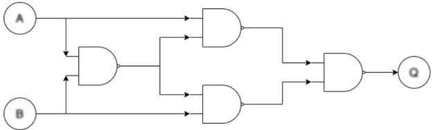
The image depicts a logic circuit diagram composed of AND gates. The circuit takes two inputs, A and B, and produces a single output, Q. The diagram shows the arrangement of the AND gates and the flow of signals through the circuit.
### Components/Axes
* **Inputs:**
* A (top-left)
* B (bottom-left)
* **Output:**
* Q (right)
* **Logic Gates:** The diagram contains four AND gates.
* **Flow Direction:** The arrows indicate the direction of signal flow from left to right.
### Detailed Analysis
1. **Input A:** The input A is fed directly into the top AND gate on the right side of the diagram. It is also fed into an AND gate on the left side of the diagram.
2. **Input B:** The input B is fed directly into the bottom AND gate on the right side of the diagram. It is also fed into the AND gate on the left side of the diagram.
3. **Left AND Gate:** The inputs A and B are fed into the left AND gate. The output of this AND gate is then fed into both the top and bottom AND gates on the right side of the diagram.
4. **Top Right AND Gate:** This AND gate takes input A and the output of the left AND gate.
5. **Bottom Right AND Gate:** This AND gate takes input B and the output of the left AND gate.
6. **Output AND Gate:** The outputs of the top and bottom AND gates on the right side of the diagram are fed into the final AND gate, which produces the output Q.
### Key Observations
* The circuit uses multiple AND gates to perform a more complex logical operation.
* The inputs A and B are used directly and also combined through an initial AND gate.
* The output Q is the result of combining the direct inputs with the result of the initial AND operation.
### Interpretation
The diagram represents a complex AND gate circuit. The circuit's logic can be described as follows: The output Q is true if and only if both (A AND B) AND (A AND B) are true. The initial AND gate combines A and B, and this result is then used in conjunction with the original A and B inputs in the subsequent AND gates. The final AND gate combines the outputs of these intermediate AND gates to produce the final output Q. This circuit effectively implements a more complex logical function than a simple AND gate.