## Diagram: Transformation of Layered System Components
### Overview
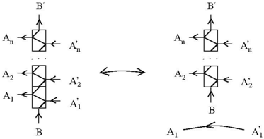
The image depicts two interconnected diagrams representing a layered system transformation. The left diagram shows a vertical stack of components (A₁, A₂, ..., Aₙ) with bidirectional arrows to their primed counterparts (A'₁, A'₂, ..., A'_ₙ), while the right diagram simplifies the structure by connecting A₁ directly to A'₁ via a curved arrow. Both diagrams include a terminal component labeled "B" at the base.
### Components/Axes
- **Left Diagram**:
- **Vertical Stack**: Labeled A₁ (bottom), A₂, ..., Aₙ (top).
- **Bidirectional Arrows**: Connect each Aᵢ to A'_ᵢ (e.g., A₁ ↔ A'₁, A₂ ↔ A'₂).
- **Terminal Node**: Labeled "B" at the bottom.
- **Right Diagram**:
- **Simplified Stack**: Same Aᵢ and A'_ᵢ labels but only A₁ ↔ A'₁ is explicitly shown with a curved arrow.
- **Terminal Node**: Labeled "B" at the bottom.
- **Bidirectional Arrow**: Connects the left and right diagrams, suggesting equivalence or transformation.
### Detailed Analysis
- **Left Diagram**:
- Each Aᵢ component has a straight bidirectional arrow to A'_ᵢ, implying direct, linear relationships or transformations.
- The vertical stacking suggests hierarchical or sequential dependencies.
- **Right Diagram**:
- The curved arrow between A₁ and A'₁ may indicate a non-linear, indirect, or more complex relationship compared to the left diagram.
- The absence of intermediate A₂–Aₙ components in the right diagram implies simplification or abstraction.
### Key Observations
1. **Bidirectional Relationships**: All Aᵢ ↔ A'_ᵢ connections are reversible, suggesting symmetry in the system's behavior.
2. **Hierarchical Structure**: The left diagram emphasizes layered dependencies, while the right diagram abstracts this into a single direct relationship.
3. **Curved Arrow Significance**: The curved arrow in the right diagram could represent a feedback loop, non-linear process, or emergent property not present in the left diagram.
### Interpretation
The diagrams likely illustrate a **system transformation** where:
- The left diagram represents a detailed, step-by-step process (e.g., data flow through layers A₁–Aₙ to produce A'₁–A'_ₙ, with B as an output or boundary condition).
- The right diagram abstracts this into a simplified model, where A₁ directly influences A'₁, possibly representing a higher-level equivalence or emergent behavior.
- The bidirectional arrows suggest the system is **reversible** or **symmetric**, allowing transformations in both directions.
- The terminal "B" component may act as a **boundary condition**, **output**, or **reference point** for the system.
### Notable Patterns
- The left diagram’s vertical stacking implies **cumulative or sequential processing**, while the right diagram’s simplification suggests **optimization** or **model reduction**.
- The curved arrow in the right diagram introduces ambiguity about the nature of the A₁–A'₁ relationship, requiring further context to determine if it represents a delay, feedback, or non-linear interaction.
### Conclusion
This diagram highlights the trade-off between **detailed modeling** (left) and **abstraction** (right), with the bidirectional arrow emphasizing the system’s flexibility. The curved arrow in the right diagram invites further investigation into the nature of the A₁–A'₁ relationship, potentially uncovering hidden dynamics in the system.