\n
## Diagram: Agent Interaction Flow
### Overview
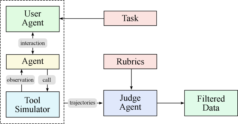
The image depicts a diagram illustrating the interaction flow between different agents and components in a system. The system involves a User Agent, an Agent, a Tool Simulator, a Judge Agent, and the concepts of Tasks, Rubrics, and Filtered Data. The diagram shows the direction of information flow between these elements using arrows labeled with the type of interaction.
### Components/Axes
The diagram consists of the following components:
* **User Agent:** Represented by a light green rectangle.
* **Agent:** Represented by a yellow rectangle.
* **Tool Simulator:** Represented by a teal rectangle.
* **Judge Agent:** Represented by a light blue rectangle.
* **Task:** Represented by a light red rectangle.
* **Rubrics:** Represented by a light orange rectangle.
* **Filtered Data:** Represented by a light green rectangle.
The following interactions are labeled on the arrows:
* **interaction:** From User Agent to Agent.
* **observation:** From Agent to Tool Simulator.
* **call:** From Agent to Tool Simulator.
* **trajectories:** From Tool Simulator to Judge Agent.
* The Judge Agent receives input from Rubrics.
* The Judge Agent outputs Filtered Data.
A dashed box encompasses the User Agent, Agent, and Tool Simulator, visually grouping them as a single unit.
### Detailed Analysis or Content Details
The diagram illustrates a closed-loop system. The User Agent initiates a process by interacting with the Agent. The Agent then observes and calls upon the Tool Simulator. The Tool Simulator generates trajectories, which are then evaluated by the Judge Agent, using Rubrics as a guide. The Judge Agent then produces Filtered Data. The User Agent receives the output of the Agent.
The diagram does not contain numerical data or specific values. It is a conceptual representation of a process.
### Key Observations
The diagram highlights the separation of concerns between the different agents. The Tool Simulator is isolated within the dashed box, suggesting it is a controlled environment. The Judge Agent acts as an evaluator, using Rubrics to assess the output of the Tool Simulator. The Filtered Data represents the refined output of the system.
### Interpretation
This diagram likely represents a system for evaluating the performance of an agent (the central yellow box) in completing tasks. The User Agent provides the task, and the Agent utilizes the Tool Simulator to generate solutions. The Judge Agent, guided by Rubrics, assesses the quality of these solutions, resulting in Filtered Data. This setup suggests a focus on iterative improvement and objective evaluation of agent behavior. The dashed box around the User Agent, Agent, and Tool Simulator indicates a self-contained unit that interacts with the external Judge Agent. The system is designed to provide a structured and measurable way to assess and refine the Agent's capabilities. The diagram is a high-level architectural overview, and does not provide details on the internal workings of each component.