## Diagram: XP-Asserted Nodes and Pre-XP Nodes Flow
### Overview
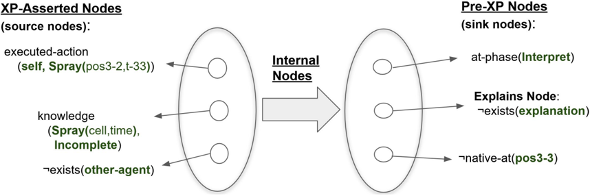
The diagram illustrates a system architecture with two primary components: **XP-Asserted Nodes (source nodes)** and **Pre-XP Nodes (sink nodes)**, connected via **Internal Nodes**. Arrows indicate directional relationships and dependencies between nodes, with labels specifying actions, knowledge states, and existential conditions.
### Components/Axes
#### Left Oval: XP-Asserted Nodes (source nodes)
- **executed-action**:
- Label: `(self, Spray(pos3-2,t-33))`
- Position: Top-left node within the oval.
- **knowledge**:
- Label: `(Spray(cell,time), Incomplete)`
- Position: Middle node within the oval.
- **exists(other-agent)**:
- Label: `¬exists(other-agent)`
- Position: Bottom node within the oval.
#### Right Oval: Pre-XP Nodes (sink nodes)
- **at-phase(Interpret)**:
- Label: `at-phase(Interpret)`
- Position: Top node within the oval.
- **Explains Node**:
- Label: `¬exists(explanation)`
- Position: Middle node within the oval.
- **native-at(pos3-3)**:
- Label: `¬native-at(pos3-3)`
- Position: Bottom node within the oval.
#### Arrows and Internal Nodes
- **Internal Nodes**:
- Label: `Internal Nodes`
- Position: Central arrow connecting the two ovals.
- **Directionality**:
- Arrows flow from XP-Asserted Nodes (left) to Pre-XP Nodes (right).
### Detailed Analysis
#### XP-Asserted Nodes (Source Nodes)
1. **executed-action**:
- Represents an action performed by the system (`self`) with parameters `Spray(pos3-2,t-33)`.
- Positioned at the top of the left oval, suggesting it is the initial or primary action.
2. **knowledge**:
- Indicates a knowledge state involving `Spray(cell,time)` with an `Incomplete` status.
- Positioned centrally, implying it is a transitional or intermediate state.
3. **exists(other-agent)**:
- A negation (`¬`) indicates the absence of another agent.
- Positioned at the bottom, possibly representing a boundary condition.
#### Pre-XP Nodes (Sink Nodes)
1. **at-phase(Interpret)**:
- Represents a phase labeled `Interpret`, likely part of a processing or analysis step.
- Positioned at the top of the right oval, suggesting it is the first step in the sink nodes.
2. **Explains Node**:
- A negation (`¬`) indicates the absence of an explanation.
- Positioned centrally, possibly reflecting a dependency or unresolved state.
3. **native-at(pos3-3)**:
- A negation (`¬`) indicates the absence of a native state at position `pos3-3`.
- Positioned at the bottom, suggesting a final or terminal condition.
#### Internal Nodes
- The central arrow labeled `Internal Nodes` connects the two ovals, acting as a mediator for data or state transitions.
### Key Observations
- **Directional Flow**: All arrows point from XP-Asserted Nodes to Pre-XP Nodes, indicating a unidirectional process.
- **Negations**: Multiple nodes use `¬` (negation), suggesting constraints or missing states (e.g., `¬exists(explanation)`, `¬native-at(pos3-3)`).
- **Incomplete Knowledge**: The `knowledge` node explicitly states `Incomplete`, highlighting a gap in the system’s understanding.
- **Positional Hierarchy**: Nodes are arranged vertically within each oval, with top nodes likely representing initial states and bottom nodes representing terminal states.
### Interpretation
This diagram models a system where **XP-Asserted Nodes** (source nodes) generate or assert actions and knowledge, which are then processed through **Internal Nodes** to produce **Pre-XP Nodes** (sink nodes). Key insights:
1. **Knowledge Gaps**: The `Incomplete` status of the `knowledge` node and the absence of explanations (`¬exists(explanation)`) suggest unresolved dependencies or missing data.
2. **Agent Constraints**: The negation `¬exists(other-agent)` implies the system operates in isolation or lacks external agents.
3. **Phase Dependency**: The `at-phase(Interpret)` node indicates a critical phase in the sink nodes, possibly requiring interpretation of prior actions.
4. **Structural Rigidity**: The unidirectional flow and fixed node positions suggest a deterministic process with no feedback loops.
### Notes on Data and Uncertainty
- **No Numerical Data**: The diagram lacks quantitative values, focusing instead on logical relationships and states.
- **Textual Labels**: All information is textual, with no visual data points or trends to analyze.
- **Color Coding**: No explicit legend is present, but labels are highlighted in green (e.g., `Spray`, `Interpret`, `explanation`), possibly for emphasis.
This diagram serves as a conceptual model for understanding the flow of actions, knowledge, and constraints within a system, emphasizing dependencies and unresolved states.