\n
## Diagram: Memory Bank Access Timing with RFM Mask
### Overview
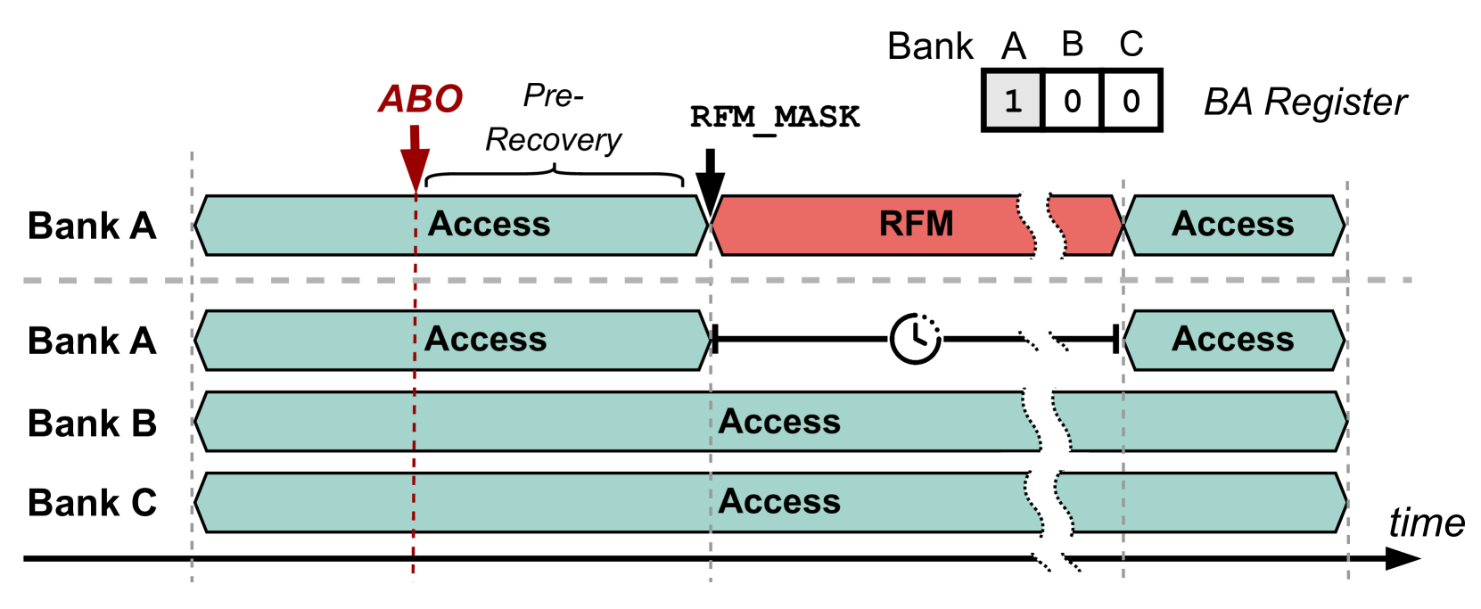
This diagram illustrates the timing of access operations to multiple memory banks (A, B, and C) in relation to a Recovery Failure Mask (RFM) operation. The diagram uses a timeline to show the sequence of "Access" and "RFM" operations, and includes a "BA Register" indicating the bank activation status. The diagram appears to be explaining a process for handling memory recovery failures.
### Components/Axes
* **Banks:** A, B, and C are the memory banks being accessed.
* **Time:** The horizontal axis represents time, flowing from left to right.
* **BA Register:** A small table in the top-right corner showing the activation status of each bank (1 = active, 0 = inactive). The banks are labeled A, B, and C.
* **ABO:** An arrow labeled "ABO" pointing downwards, indicating a trigger or signal.
* **Pre-Recovery:** Text label indicating a phase before recovery.
* **RFM_MASK:** Text label indicating the application of a Recovery Failure Mask.
* **RFM:** A red block representing the Recovery Failure Mask operation.
* **Access:** A teal block representing a memory access operation.
* **Clock Icon:** A circular arrow with a clock face inside, indicating a delay or timing element.
### Detailed Analysis or Content Details
The diagram shows the following sequence of events:
1. **Initial State:** All banks (A, B, and C) are initially in an "Access" state. The BA Register shows Bank A is active (1), while Banks B and C are inactive (0).
2. **ABO Trigger:** An "ABO" signal is received, initiating a pre-recovery phase.
3. **Bank A RFM:** Bank A experiences an RFM operation (represented by the red block). This occurs after the "ABO" signal and is indicated by the "RFM_MASK" label.
4. **Bank A Delay:** After the RFM operation on Bank A, there is a delay indicated by the clock icon.
5. **Bank A Access Resumption:** Following the delay, Bank A resumes "Access" operations.
6. **Bank B & C Access:** Banks B and C continue "Access" operations throughout the sequence.
The BA Register remains unchanged throughout the sequence, with Bank A active and Banks B and C inactive.
### Key Observations
* The RFM operation only affects Bank A.
* There is a noticeable delay after the RFM operation on Bank A before access can resume.
* Banks B and C are not directly impacted by the RFM operation.
* The diagram focuses on the timing and sequence of events rather than specific data values.
### Interpretation
This diagram likely illustrates a fault tolerance or error recovery mechanism in a memory system. The "ABO" signal could represent a detected error condition. The "RFM" operation is a corrective action applied specifically to Bank A, potentially to mask a faulty memory location or refresh data. The delay after the RFM operation suggests a stabilization period or a time required for the mask to take effect. The BA Register indicates that the bank activation status remains consistent throughout the process, suggesting that the RFM operation doesn't involve deactivating or re-activating the bank.
The diagram demonstrates a system's ability to isolate and recover from errors in a specific memory bank without disrupting operations in other banks. The use of a mask suggests a targeted approach to error handling, rather than a complete system reset. The diagram is a high-level illustration of the process and does not provide details about the specific error detection or masking mechanisms.