## Analog Neural Network Architecture Diagrams
### Overview
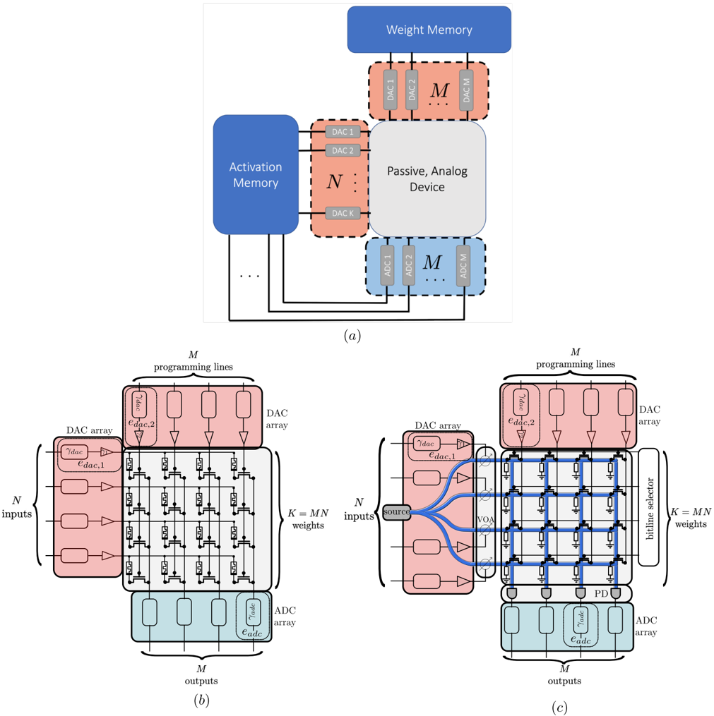
The image presents three technical diagrams (a, b, c) illustrating components and signal flow in an analog neural network architecture. Diagrams (b) and (c) show detailed implementations of matrix multiplication operations using DAC arrays and analog devices, while diagram (a) provides a high-level system overview.
### Components/Axes
**Diagram (a): System Overview**
- **Activation Memory**: Blue block with N DAC arrays (DAC1 to DACk)
- **Weight Memory**: Blue block with M DAC arrays (DAC1 to DACm)
- **Passive Analog Device**: Central gray block connecting memories
- **Signal Flow**: Arrows show data path from Activation Memory → Weight Memory via analog device
- **Key Elements**: Programming lines, DAC arrays, memory blocks
**Diagram (b): Matrix Multiplication Core**
- **Inputs**: N DAC arrays on left (vertical stack)
- **Outputs**: M DAC arrays at bottom (horizontal stack)
- **Grid Structure**: N×M DAC array matrix with programming lines
- **Weight Configuration**: K = MN programmable weights
- **Color Coding**: Pink (input DACs), Blue (output DACs), Gray (analog device)
**Diagram (c): Enhanced Analog Device**
- **Additional Components**:
- Bitline Selector (blue vertical lines)
- Voltage Source (V_OA)
- Programming Lines (top connections)
- **Signal Path**: Inputs → DAC arrays → Bitline Selector → Analog Device → Output DAC arrays
- **Control Elements**: Voltage-controlled switches (VOA) in blue
### Detailed Analysis
**Diagram (a)**
- Activation Memory (N DACs) and Weight Memory (M DACs) are spatially separated but connected through the Passive Analog Device
- DAC arrays use dashed-line boundaries with labeled DAC1-DACk/m notation
- Programming lines connect all components, suggesting reconfigurable architecture
**Diagram (b)**
- Grid of N×M DAC arrays forms the computation matrix
- Inputs enter vertically (N channels), outputs exit horizontally (M channels)
- Programming lines run horizontally across the grid, enabling weight configuration
- K = MN weights implies full connectivity between input and output layers
**Diagram (c)**
- Bitline Selector introduces vertical control lines between DAC arrays
- Voltage Source (V_OA) enables dynamic control of analog paths
- Blue control lines show additional signal routing compared to diagram (b)
- Maintains N×M DAC array structure but adds selection capability
### Key Observations
1. **DAC Array Consistency**: All diagrams use identical DAC array notation (DAC1-DACk/m) with consistent pink/blue coloring
2. **Signal Flow Evolution**: Diagram (a) shows conceptual flow, (b) implements matrix structure, (c) adds control mechanisms
3. **Component Scaling**: N inputs and M outputs maintain consistent positioning across diagrams
4. **Control Complexity**: Diagram (c) introduces 2× more control elements (VOA switches + bitline selector) vs diagram (b)
### Interpretation
This architecture demonstrates a hybrid digital-analog computing system where:
1. **Digital Components** (DAC arrays) handle data storage and input/output conversion
2. **Analog Processing** occurs in the central Passive Analog Device, enabling parallel computation
3. **Programmability** is achieved through reconfigurable programming lines and bitline selectors
4. **Efficiency Gains** come from analog matrix multiplication (O(1) complexity vs digital O(N²))
The progression from (a)→(b)→(c) reveals increasing implementation detail, showing how analog computing can accelerate neural network operations while maintaining digital control. The bitline selector in (c) suggests potential for dynamic weight masking or sparse computation optimization.