## Diagram: Beta Reduction
### Overview
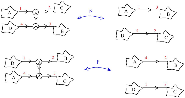
The image depicts two diagrams illustrating beta reduction steps in a computational process. Each diagram shows a transformation from a complex structure on the left to a simplified structure on the right, connected by a blue double-headed arrow labeled "β". The diagrams involve nodes labeled A, B, C, and D, along with lambda (λ) and application (Y) symbols, and directed edges numbered 1, 2, 3, and 4.
### Components/Axes
* **Nodes:** Represented by irregular shapes, labeled A, B, C, and D.
* **Lambda Abstraction (λ):** Represented by a circle containing the lambda symbol.
* **Application (Y):** Represented by a circle containing the application symbol.
* **Edges:** Represented by arrows, labeled with numbers 1, 2, 3, and 4 in red.
* **Beta Reduction (β):** Represented by a blue double-headed arrow labeled "β".
### Detailed Analysis
**Top Diagram:**
* **Left Side:**
* Node A has an outgoing edge (1) to a lambda abstraction (λ).
* Node D has an outgoing edge (4) to an application (Y).
* The lambda abstraction (λ) has an outgoing edge (2) to node C.
* The application (Y) has an outgoing edge (3) to node B.
* The lambda abstraction (λ) and application (Y) are connected by a vertical edge.
* **Right Side:**
* Node A has an outgoing edge (1) to node B, labeled with number 3.
* Node D has an outgoing edge (4) to node C, labeled with number 2.
**Bottom Diagram:**
* **Left Side:**
* Node D has an outgoing edge (1) to a lambda abstraction (λ).
* Node A has an outgoing edge (4) to an application (Y).
* The lambda abstraction (λ) has an outgoing edge (2) to node B.
* The application (Y) has an outgoing edge (3) to node C.
* The lambda abstraction (λ) and application (Y) are connected by a vertical edge.
* **Right Side:**
* Node A has an outgoing edge (4) to node B, labeled with number 2.
* Node D has an outgoing edge (1) to node C, labeled with number 3.
### Key Observations
* The diagrams illustrate a transformation process, likely a form of beta reduction in lambda calculus or a related computational model.
* The "β" symbol indicates the application of a beta reduction rule.
* The numbered edges likely represent the order or dependencies in the reduction process.
* The lambda abstraction and application symbols suggest function application and abstraction operations.
### Interpretation
The diagrams demonstrate how a complex expression involving lambda abstractions and applications can be simplified through beta reduction. The transformation involves rearranging the connections between nodes A, B, C, and D, effectively substituting the argument into the function body. The numbered edges likely represent the flow of data or the order of operations during the reduction. The two diagrams show different initial configurations and their corresponding reduced forms, highlighting the versatility of the beta reduction process.