\n
## Diagram: Quantum State Representation and Optical Setup
### Overview
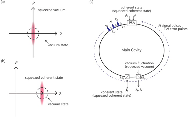
The image presents a diagram illustrating quantum states of light and an optical setup for generating and manipulating them. It consists of three panels: (a) and (b) depict phase space representations of quantum states, while (c) shows a schematic of an optical cavity setup. The diagram appears to relate to quantum optics, specifically squeezed states of light and their use in quantum information processing.
### Components/Axes
* **Panel (a):** Axes labeled 'X' (horizontal) and 'P' (vertical). Displays a phase space representation with a vertically elongated ellipse labeled "squeezed vacuum" and a circular shape labeled "vacuum state".
* **Panel (b):** Axes labeled 'X' (horizontal) and 'P' (vertical). Displays a phase space representation with a horizontally elongated ellipse labeled "squeezed coherent state" and a circular shape labeled "vacuum state".
* **Panel (c):** Contains several labeled components:
* "Main Cavity" – a large, shaded circular region.
* "PSA" – positioned at the top of the Main Cavity.
* "x₁", "x₂", "xN" – Input ports to the Main Cavity.
* "e₁", "e₂", "eN" – Output ports from the Main Cavity.
* "BS₁" and "BS₂" – Beam splitters positioned at the bottom of the Main Cavity.
* "h₁" and "h₂" – Input ports to the Beam Splitters.
* "x₁, e₁" – Output ports from the Beam Splitters.
* Labels indicating states: "coherent state (squeezed coherent state)", "vacuum fluctuation (squeezed vacuum)".
* Text: "N signal pulses + N error pulses" – positioned near the top of the Main Cavity.
### Detailed Analysis / Content Details
* **Panel (a):** The "squeezed vacuum" ellipse is oriented vertically, indicating squeezing in the X quadrature. The "vacuum state" is represented as a circle centered at the origin, indicating equal uncertainty in both X and P quadratures.
* **Panel (b):** The "squeezed coherent state" ellipse is oriented horizontally, indicating squeezing in the P quadrature. The "vacuum state" is again represented as a circle.
* **Panel (c):** The "Main Cavity" is a central element. A "coherent state (squeezed coherent state)" is input into the cavity via ports x₁, x₂, and xN. The cavity generates "vacuum fluctuations (squeezed vacuum)". The output is a combination of "N signal pulses + N error pulses" exiting via ports e₁, e₂, and eN. The beam splitters BS₁ and BS₂ are used to combine the input coherent state with the vacuum fluctuations. The coherent state is also input via h₁ and h₂.
### Key Observations
* The diagram illustrates the concept of squeezing, where the uncertainty in one quadrature of a quantum state is reduced at the expense of increased uncertainty in the other.
* Panel (a) shows squeezing of the vacuum state, while Panel (b) shows squeezing of a coherent state.
* Panel (c) depicts a setup for generating and manipulating squeezed states within an optical cavity.
* The presence of "N signal pulses + N error pulses" suggests the setup is used for quantum communication or computation, where errors are a consideration.
### Interpretation
The diagram demonstrates a method for generating and utilizing squeezed states of light. Squeezed states are non-classical states of light with reduced noise in one quadrature, which can be used to enhance the sensitivity of measurements or improve the performance of quantum communication protocols. The optical cavity in Panel (c) provides a means to enhance the interaction between the input coherent state and the vacuum fluctuations, leading to the generation of squeezed states. The inclusion of signal and error pulses suggests that this setup is being used in a context where quantum information is being processed, and the effects of noise and errors are being considered. The different orientations of the squeezed ellipses in Panels (a) and (b) indicate that squeezing can be achieved in different quadratures, depending on the specific setup and desired application. The diagram is a conceptual representation of a complex quantum optical system, and the specific details of the implementation would depend on the particular experimental setup.