## Diagram: System Architecture for Compute-In-Memory Processing
### Overview
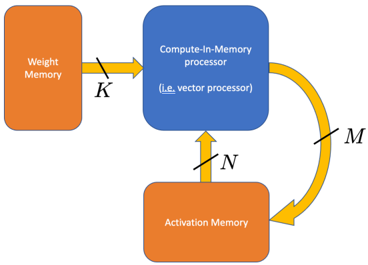
The diagram illustrates a system architecture for compute-in-memory processing, emphasizing data flow between three key components: Weight Memory, Compute-In-Memory processor, and Activation Memory. Arrows labeled with variables (K, N, M) indicate directional data transfer, forming a closed-loop system with iterative processing capabilities.
### Components/Axes
1. **Weight Memory** (orange block, left side):
- Labeled explicitly as "Weight Memory"
- Connected via arrow labeled **K** to the Compute-In-Memory processor
2. **Compute-In-Memory processor** (blue block, center):
- Labeled "Compute-In-Memory processor"
- Subtext clarifies: "(i.e., vector processor)"
- Receives input from Weight Memory (**K**)
- Outputs data to Activation Memory (**M**)
- Receives feedback from Activation Memory (**N**)
3. **Activation Memory** (orange block, bottom):
- Labeled explicitly as "Activation Memory"
- Connected via arrow labeled **M** to the Compute-In-Memory processor
- Provides feedback to the processor via arrow labeled **N**
4. **Data Flow**:
- **K**: Weight Memory → Compute-In-Memory processor
- **M**: Compute-In-Memory processor → Activation Memory
- **N**: Activation Memory → Compute-In-Memory processor (feedback loop)
### Detailed Analysis
- **Component Relationships**:
- Weight Memory and Activation Memory are both orange, suggesting similar functional roles (likely data storage).
- The Compute-In-Memory processor (blue) acts as the central processing unit, integrating inputs from both memory types.
- The feedback loop (**N**) implies iterative computation, where outputs from Activation Memory are reused as inputs for subsequent processing cycles.
- **Variable Labels**:
- **K**: Likely represents weight data (e.g., neural network parameters) fed into the processor.
- **M**: Output from the processor to Activation Memory, possibly intermediate results or updated activations.
- **N**: Feedback signal from Activation Memory, enabling recurrent or adaptive processing.
### Key Observations
1. **Closed-Loop System**: The architecture forms a cycle (Weight Memory → Processor → Activation Memory → Processor), enabling continuous computation without external data input after initialization.
2. **Parallelism**: The Compute-In-Memory processor is explicitly labeled as a vector processor, indicating support for parallel operations critical for high-throughput tasks like matrix multiplications in AI/ML.
3. **Memory Hierarchy**: Weight Memory and Activation Memory are distinct but interconnected, reflecting a tiered memory structure optimized for specific computational phases.
### Interpretation
This diagram represents a hardware/software co-design for efficient computation, likely targeting applications such as neural network inference or real-time signal processing. The compute-in-memory approach minimizes data movement between separate processing and memory units, reducing latency and energy consumption. The feedback loop (**N**) suggests the system can adapt dynamically, potentially implementing recurrent neural networks or adaptive filtering algorithms. The use of a vector processor highlights optimization for batch operations, aligning with the parallel nature of matrix-based computations common in machine learning. The orange color coding for both memory blocks may imply shared architectural characteristics (e.g., non-volatile memory, in-memory computing arrays).