## Diagram: Transformation Process Between States A and B
### Overview
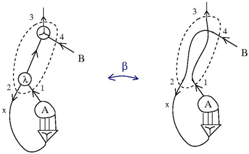
The image depicts two interconnected diagrams labeled **A** and **B**, connected by a bidirectional arrow labeled **β**. Each diagram contains labeled components (1–4), a central node (λ), and a shared external element (x). The diagrams suggest a dynamic relationship or transformation process between states A and B.
---
### Components/Axes
- **Left Diagram (State A)**:
- **Components**:
- **A**: Central node with three downward arrows (possibly representing outputs or dependencies).
- **x**: External input/output at the bottom-left.
- **λ**: Central node with three outward arrows (labeled 1, 2, 3).
- **B**: External node connected to λ via arrow 4.
- **Labels**:
- Arrows: 1 (λ → A), 2 (x → λ), 3 (λ → x), 4 (λ → B).
- Nodes: A, B, λ, x.
- **Right Diagram (State B)**:
- **Components**:
- **A**: Central node with three downward arrows (similar to State A).
- **x**: External input/output at the bottom-left.
- **λ**: Central node with three outward arrows (labeled 1, 2, 3).
- **B**: External node connected to λ via arrow 4.
- **Labels**:
- Arrows: 1 (λ → A), 2 (x → λ), 3 (λ → x), 4 (λ → B).
- Nodes: A, B, λ, x.
- **Bidirectional Arrow (β)**: Connects the two diagrams, suggesting a reversible or iterative relationship between states A and B.
---
### Detailed Analysis
- **Left Diagram (State A)**:
- **Flow**:
1. **x** feeds into **λ** via arrow 2.
2. **λ** distributes outputs to **A** (arrow 1), **x** (arrow 3), and **B** (arrow 4).
3. **A** receives input from **λ** and generates three outputs (downward arrows).
- **Key Relationships**:
- **λ** acts as a hub, mediating interactions between **x**, **A**, and **B**.
- **B** is an external node dependent on **λ**.
- **Right Diagram (State B)**:
- **Flow**:
1. **x** feeds into **λ** via arrow 2.
2. **λ** distributes outputs to **A** (arrow 1), **x** (arrow 3), and **B** (arrow 4).
3. **A** receives input from **λ** and generates three outputs (downward arrows).
- **Key Relationships**:
- **λ** maintains the same role as in State A.
- **B** remains an external node dependent on **λ**.
- **Bidirectional Arrow (β)**:
- Indicates a transformation or equivalence between states A and B.
- Suggests the system can transition between these states while preserving core relationships (e.g., **λ** as a central mediator).
---
### Key Observations
1. **Symmetry**: Both diagrams share identical structural components (A, B, λ, x) and arrow labels (1–4), implying a consistent underlying mechanism.
2. **Central Node (λ)**: Acts as a critical mediator in both states, distributing inputs/outputs.
3. **External Node (B)**: Dependent on **λ** in both diagrams, suggesting it is an output or dependent variable.
4. **Bidirectional Relationship (β)**: Implies the system can evolve between states A and B without losing core functionality.
---
### Interpretation
The diagrams likely represent a **state transition** or **process equivalence** in a technical or mathematical system. The bidirectional arrow **β** suggests that states A and B are interchangeable or part of a cyclical process. The central node **λ** serves as a pivotal component, maintaining system integrity during transitions. The external node **B** and input **x** highlight dependencies on external factors, while the downward arrows from **A** may represent outputs or downstream effects. This structure could model concepts like **feedback loops**, **state machines**, or **equivalence classes** in engineering, computer science, or physics.