TECHNICAL ASSET FINGERPRINT
6227751a0e023916ea64010e
Click to view fullscreen
Press ESC or click to close
FOUND IN PAPERS
EXPERT: healer-alpha-free VERSION 1
RUNTIME: free/openrouter/healer-alpha
INTEL_VERIFIED
## Mathematical Diagram: Commutative Diagram of Transformations
### Overview
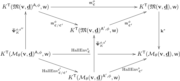
The image displays a complex commutative diagram from the fields of category theory, formal methods, or theoretical computer science. It illustrates a network of mathematical objects (nodes) and the transformations or mappings (arrows) between them. The diagram is structured as a square with additional central nodes and cross-connections, suggesting relationships between different representations or models under various operations.
### Components/Axes
The diagram consists of **8 distinct nodes** (mathematical expressions) and **10 labeled arrows** connecting them. There are no traditional chart axes; the structure is purely relational.
**Nodes (Mathematical Objects):**
1. **Top-Left:** `K^T(𝔐(v, d)^A, φ, w)`
2. **Top-Center:** `K^T(𝔐(v, d)^A', φ, w)`
3. **Top-Right:** `K^T(𝔐(v, d), w)`
4. **Middle-Left:** `K^T(M_θ(v, d)^A, φ, w)`
5. **Center:** `K^T(M_θ(v, d)^A', φ, w)`
6. **Middle-Right:** `K^T(M_θ(v, d), w)`
7. **Bottom-Left:** `K^T(M_θ(v, d)^A, φ, w)` (Note: This appears identical to node 4, suggesting a potential duplicate or a specific state in the flow.)
8. **Bottom-Center:** `K^T(M_θ(v, d)^A', φ, w)` (Note: This appears identical to node 5.)
9. **Bottom-Right:** `K^T(M_θ(v, d), w)` (Note: This appears identical to node 6.)
*Clarification:* The diagram's spatial layout suggests a 2x3 grid (2 rows, 3 columns) with additional vertical connections. The nodes in the "bottom row" of the visual layout are actually the same expressions as those in the "middle row," indicating they represent the same object in different parts of the diagram's flow.
**Arrows (Transformations/Mappings):**
* **Horizontal Arrows (Top Row):**
* From Top-Left to Top-Center: `m_φ^{e/e'}`
* From Top-Center to Top-Right: `m_φ^{e'}`
* From Top-Left to Top-Right (direct, above): `m_φ^{e}`
* **Horizontal Arrows (Bottom Row):**
* From Middle-Left to Center: `HallEnv_{e/e'}`
* From Center to Middle-Right: `HallEnv_{e'}`
* From Middle-Left to Middle-Right (direct, above): `HallEnv_{e}`
* **Vertical Arrows:**
* From Top-Left to Middle-Left: `Ψ_K^{φ, s''}`
* From Top-Center to Center: `Ψ_K^{φ, s'}`
* From Top-Right to Middle-Right: `k*`
* **Diagonal Arrows:**
* From Top-Left to Center: `m_φ^{e/e'}` (This label is shared with the horizontal arrow from Top-Left to Top-Center, indicating the same transformation applied in a different context.)
* From Top-Center to Middle-Right: `m_φ^{e'}` (This label is shared with the horizontal arrow from Top-Center to Top-Right.)
### Detailed Analysis
**Symbol Transcription & Structure:**
* **Common Elements:** All nodes are of the form `K^T( ... )`. The arguments inside the parentheses vary.
* **Core Objects:** Two primary objects appear to be transformed:
1. `𝔐(v, d)` and its variants (`𝔐(v, d)^A`, `𝔐(v, d)^A'`). The symbol `𝔐` is a script capital M.
2. `M_θ(v, d)` and its variants (`M_θ(v, d)^A`, `M_θ(v, d)^A'`). This includes a subscript `θ`.
* **Parameters:** The objects are parameterized by `v`, `d`, `φ`, and `w`. The superscripts `A` and `A'` likely denote different abstraction levels, versions, or annotations.
* **Transformations:**
* `m_φ^{...}`: A family of mappings (likely "model" or "morphism") parameterized by `φ` and indexed by `e`, `e'`, and `e/e'`.
* `HallEnv_{...}`: A family of transformations (likely "Hallucination Environment" or a similar construct in formal verification) indexed similarly.
* `Ψ_K^{φ, s...}`: Vertical mappings (likely "projection" or "simulation" relations) parameterized by `φ` and a state `s` (`s'`, `s''`).
* `k*`: A specific mapping from the top-right to the middle-right node.
**Spatial Grounding & Flow:**
The diagram is organized into two parallel horizontal flows:
1. **Top Flow (𝔐-based):** Starts with an abstracted version `𝔐(v, d)^A`, moves to a primed version `𝔐(v, d)^A'` via `m_φ^{e/e'}`, and finally to the base object `𝔐(v, d)` via `m_φ^{e'}`. A direct path `m_φ^{e}` also exists.
2. **Bottom Flow (M_θ-based):** Mirrors the top flow but operates on `M_θ(v, d)` variants using `HallEnv` transformations.
These two flows are connected vertically by the `Ψ_K` mappings and the `k*` mapping, creating a commutative structure. The diagonal arrows reinforce that the same transformations (`m_φ^{e/e'}`, `m_φ^{e'}`) can be applied across different levels of the diagram.
### Key Observations
1. **Symmetry and Commutativity:** The diagram's primary feature is its commutative nature. The existence of multiple paths between nodes (e.g., from Top-Left to Middle-Right can go via Top-Center and Center, or directly via Middle-Left and Middle-Right) implies that the composition of transformations along these paths yields equivalent results.
2. **Dual Representation:** The diagram explicitly contrasts two representations of a system: one using `𝔐` (possibly a theoretical or ideal model) and another using `M_θ` (possibly a parameterized, learned, or concrete model).
3. **Abstraction Hierarchy:** The superscripts `A` and `A'` suggest a hierarchy of abstractions or refinements, with transformations (`m`, `HallEnv`) moving between these levels.
4. **Parameter Consistency:** Parameters `v`, `d`, `φ`, and `w` are consistently present across all nodes, indicating they are fundamental to the system being modeled.
### Interpretation
This diagram is a formal, graphical representation of relationships between different models or specifications of a system, likely within the context of **machine learning verification, formal methods, or program semantics**.
* **What it Demonstrates:** It shows how a high-level, abstract model (`𝔐(v, d)^A`) can be related to a concrete, parameterized model (`M_θ(v, d)`) through a series of refinement steps (`m_φ`, `HallEnv`) and abstraction mappings (`Ψ_K`). The commutativity asserts the consistency of these relationships—different sequences of refinement and abstraction lead to the same result.
* **Relationships Between Elements:** The `Ψ_K` mappings likely represent **simulation** or **refinement relations** that connect the abstract (`𝔐`) and concrete (`M_θ`) worlds. The `m_φ` and `HallEnv` transformations represent operations that modify the level of abstraction or detail within each world. The `k*` mapping provides a direct link from the fully refined abstract model to the concrete model.
* **Notable Implications:** The structure suggests a framework for **proving properties** about a learned model (`M_θ`) by relating it to a trusted abstract specification (`𝔐`). If a property holds for `𝔐`, and the diagram's commutativity holds, the property can be transferred to `M_θ` via the `Ψ_K` and `k*` mappings. The "HallEnv" label is particularly suggestive of a context involving **hallucination** or **environment modeling** in AI systems, where formal guarantees are sought.
* **Underlying Message:** The diagram is a blueprint for a **correctness argument**. It visually encodes the theorem that the concrete system (`M_θ`) is a valid implementation or approximation of the abstract system (`𝔐`), with all intermediate steps and relationships explicitly defined and verified to be consistent.
DECODING INTELLIGENCE...