## Diagram: Reachability Models (RM) for Agents A1, A2, A3
### Overview
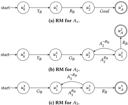
The image presents three distinct Reachability Models (RM) for agents A1, A2, and A3. Each model illustrates a state transition system with nodes representing states (e.g., `u0`, `u1`, `uA`) and edges labeled with transition conditions (e.g., `YB`, `RB`, `GB`, `A2^RB`, `A3^RB`). The diagrams emphasize differences in state connectivity and transition logic between agents.
### Components/Axes
- **Nodes**:
- Labeled as `u0` (start), `u1`, `u2`, `u3`, and `uA` (goal).
- Nodes are enclosed in circles, with `uA` highlighted by a double border in all diagrams.
- **Edges**:
- Directed arrows represent transitions between states.
- Labels on edges include:
- `YB` (Yes/No condition?), `RB` (Reachability?), `GB` (Goal condition?), `A2^RB`, `A3^RB` (agent-specific transitions).
- **Diagram Structure**:
- **Diagram (a)**: Linear path from `start` → `u0` → `u1` → `u2` → `uA` (Goal).
- **Diagram (b)**: Path with a loop: `start` → `u0` → `u1` → `u2` → `u3` (via `A2^RB`) → `uA`.
- **Diagram (c)**: Path with a loop: `start` → `u0` → `u1` → `u2` (via `A3^RB`) → `u3` → `uA`.
### Detailed Analysis
- **Diagram (a) (RM for A1)**:
- Simplest structure: Direct linear progression from `u0` to `uA` via `u1` and `u2`.
- Edges: `YB` (start→u0), `RB` (u1→u2), `Goal` (u2→uA).
- **Diagram (b) (RM for A2)**:
- Introduces a loop between `u2` and `u3` via `A2^RB` (u2→u3) and `RB` (u3→uA).
- Additional edge `GB` (u1→u2) suggests a goal-related transition.
- **Diagram (c) (RM for A3)**:
- Loop between `u1` and `u2` via `A3^RB` (u1→u2) and `RB` (u2→u3).
- Edge `GB` (u0→u1) indicates a goal-related transition at an earlier stage.
### Key Observations
1. **Agent-Specific Transitions**:
- A1 follows a linear path without loops.
- A2 and A3 include loops (`A2^RB`, `A3^RB`), implying conditional or iterative behaviors.
2. **Transition Labels**:
- `YB`, `RB`, and `GB` appear consistently but with varying roles across diagrams.
- `A2^RB` and `A3^RB` suggest agent-specific reachability conditions.
3. **Goal State (`uA`)**:
- Always the terminal node, marked distinctly with a double border.
### Interpretation
The diagrams model how agents A1, A2, and A3 navigate state spaces to achieve a goal (`uA`).
- **A1’s Model**: Represents a straightforward, deterministic path with no branching or loops.
- **A2’s Model**: The loop (`A2^RB`) implies a conditional retry or alternative route, possibly for handling failures or optimizing reachability.
- **A3’s Model**: The earlier `GB` transition (u0→u1) suggests goal-oriented actions are prioritized early in the process.
The use of superscripts (`A2^RB`, `A3^RB`) may denote inverse or specialized reachability conditions unique to each agent. These models could represent decision-making frameworks where agents adapt their strategies based on environmental conditions (e.g., `YB` for yes/no checks, `RB` for reachability constraints).
### Notable Patterns
- **Increasing Complexity**: From A1 to A3, the models grow more complex, with added loops and agent-specific transitions.
- **Shared Elements**: All diagrams share `YB`, `RB`, and `GB`, indicating common transition types across agents.
- **Goal-Centric Design**: The terminal state `uA` is consistently emphasized, highlighting its critical role in all models.