## System Diagram: Module Interaction
### Overview
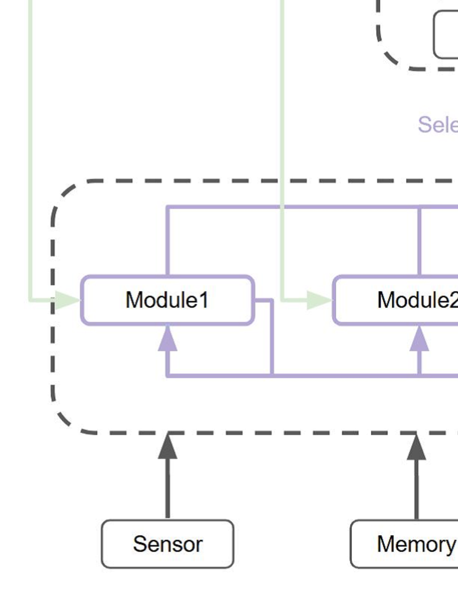
The image presents a system diagram illustrating the interaction between different modules, a sensor, and memory, all potentially managed by a selector. The diagram uses boxes to represent components and arrows to indicate the flow of information or control.
### Components/Axes
* **Components:**
* Sensor
* Memory
* Module 1
* Module 2
* Selector (partially visible)
* **Flow Indicators:** Arrows indicate the direction of data or control flow.
* **Containers:** Dashed lines enclose Module 1 and Module 2, and the Selector.
### Detailed Analysis or ### Content Details
* **Sensor:** A box labeled "Sensor" at the bottom-left. An arrow points upwards from the Sensor to Module 1.
* **Memory:** A box labeled "Memory" at the bottom-right. An arrow points upwards from the Memory to Module 2.
* **Module 1:** A rounded rectangle labeled "Module 1". It receives input from the Sensor and sends output to Module 2. It also receives input from Module 2.
* **Module 2:** A rounded rectangle labeled "Module 2". It receives input from Memory and Module 1. It also sends input to Module 1.
* **Selector:** Located at the top of the diagram, only partially visible. The text "Selector" is visible. It sends a signal to both Module 1 and Module 2.
* **Connections:**
* A purple arrow goes from the Sensor to Module 1.
* A purple arrow goes from the Memory to Module 2.
* A light green arrow goes from the Selector to Module 1.
* A light green arrow goes from the Selector to Module 2.
* A purple arrow goes from Module 1 to Module 2.
* A purple arrow goes from Module 2 to Module 1.
### Key Observations
* The Sensor and Memory provide input to Module 1 and Module 2, respectively.
* Module 1 and Module 2 have a bi-directional connection, suggesting they exchange information.
* The Selector seems to control or influence both Module 1 and Module 2.
### Interpretation
The diagram illustrates a system where a Sensor and Memory feed data into two interacting modules, Module 1 and Module 2. The Selector component likely manages or controls the operation of these modules. The bi-directional connection between Module 1 and Module 2 suggests a feedback loop or collaborative processing. The system appears to be designed for processing data from external sources (Sensor, Memory) under the control of a Selector, with internal communication between the modules.