## Diagram: Networked System Schematic
### Overview
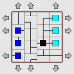
The image displays a schematic diagram of a networked system or process flow, contained within a red-bordered square. The diagram features a grid layout with interconnected colored nodes (squares) of varying types, linked by lines of different styles. Gray arrows point outward from all four sides of the border, indicating external inputs, outputs, or directional flow. The image is low-resolution and pixelated, with no embedded textual labels, titles, or legends.
### Components/Axes
* **Border:** A solid red square outline defines the system boundary.
* **Grid:** An internal, implied grid structure organizes the placement of nodes and connections.
* **Nodes (Squares):** Colored squares represent system components. Observed colors and approximate positions:
* **Dark Blue (3):** Clustered vertically on the left side of the grid.
* **Black (1):** Located in the lower-center region, acting as a central hub.
* **Light Blue (1):** Positioned in the upper-right quadrant.
* **Cyan (2):** Located on the right side, one above the other.
* **Connections (Lines):** Lines of varying styles connect the nodes:
* **Solid Black Lines:** Form the primary network paths, connecting most nodes.
* **Dashed/Dotted Lines:** Appear as secondary or alternative pathways, notably connecting the central black node to the cyan nodes on the right.
* **External Arrows:** Eight gray arrows (two per side) point radially outward from the red border, suggesting interaction with an external environment.
### Detailed Analysis
* **Spatial Layout:** The diagram is asymmetric. The left side is dominated by a vertical stack of dark blue nodes. The center features the black hub node. The right side contains the light blue and cyan nodes.
* **Connection Topology:**
* The central black node is the most connected, with solid lines linking to the dark blue cluster on the left and the light blue node above it. Dashed lines connect it to the two cyan nodes on the right.
* The dark blue nodes are interconnected vertically and link to the central black node.
* The light blue node connects to the central black node and appears to have a dashed line extending towards the upper cyan node.
* The two cyan nodes are connected to each other via a vertical dashed line and each connects back to the central black node.
* **Flow Direction:** The external arrows imply a bidirectional or omnidirectional interface with the surroundings. The internal line styles (solid vs. dashed) may indicate primary vs. secondary, or different types of flow (e.g., data, power, material).
### Key Observations
1. **Central Hub:** The black node is the topological center of the network, connecting all other colored node groups.
2. **Clustered Inputs/Outputs:** The dark blue nodes form a distinct cluster, possibly representing a set of similar inputs or a subsystem. The cyan nodes form another pair on the opposite side.
3. **Dual Connection Types:** The use of both solid and dashed lines suggests the system has at least two distinct types of relationships or pathways between components.
4. **Lack of Textual Annotation:** The diagram conveys information purely through color, shape, line style, and spatial arrangement, with no explanatory text.
### Interpretation
This diagram represents a **centralized network architecture**. The black node likely functions as a core processor, controller, or router. The dark blue cluster could represent a bank of sensors, input devices, or a source subsystem. The light blue and cyan nodes on the right may represent different types of output devices, actuators, or destination subsystems.
The dashed connections to the cyan nodes might indicate a secondary communication protocol, a backup pathway, or a different class of signal (e.g., control signals vs. data signals). The outward-pointing arrows emphasize that this is an open system, constantly interacting with its environment through multiple channels.
The absence of labels makes specific identification impossible, but the structure is classic for illustrating concepts in systems engineering, computer network design, or process control, where the focus is on the relationship and flow between functional blocks rather than their specific identity. The visual weight is on the **hierarchy** (central hub) and **modularity** (distinct colored groups) of the system.