## Neural Network Diagram: Logical Neural Network Architecture
### Overview
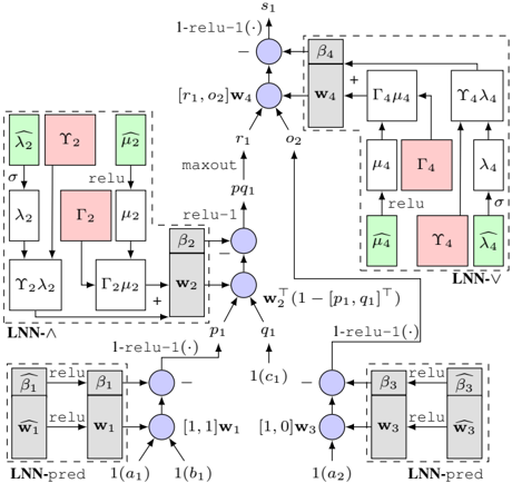
The image presents a detailed diagram of a Logical Neural Network (LNN) architecture. It illustrates the flow of data and operations between different components, including LNN-pred, LNN-∧, and LNN-∨ modules. The diagram uses nodes, blocks, and arrows to represent computations, parameters, and data dependencies.
### Components/Axes
* **Nodes:** Represented as blue circles, indicating computational units.
* **Blocks:** Represented as gray or colored rectangles, indicating parameters or intermediate values.
* **Arrows:** Indicate the direction of data flow and dependencies.
* **Labels:** Text labels are used to denote variables, parameters, and operations.
* **Modules:** Dashed boxes enclose specific LNN modules (LNN-pred, LNN-∧, LNN-∨).
**Specific Labels and Components:**
* **Top:**
* `s1`: Output node at the top.
* `1-relu-1(.)`: Operation applied to the output of the top node.
* `[r1, o2]w4`: Input to the top node.
* `β4`: Parameter block connected to the top node.
* `w4`: Parameter block connected to the top node.
* `Γ4μ4`: Intermediate value.
* `Υ4λ4`: Intermediate value.
* `μ4`: Intermediate value.
* `Γ4`: Intermediate value.
* `λ4`: Intermediate value.
* `μ̂4`: Intermediate value (green).
* `Υ4`: Intermediate value (red).
* `λ̂4`: Intermediate value (green).
* `LNN-∨`: Module label for the top-right section.
* **Middle:**
* `r1`: Input to the top node.
* `o2`: Input to the top node.
* `maxout`: Operation label.
* `pq1`: Intermediate value.
* `β2`: Parameter block connected to the middle node.
* `w2`: Parameter block connected to the middle node.
* `p1`: Input to the middle node.
* `q1`: Input to the middle node.
* `w2^T (1-[p1, q1]^T)`: Operation label.
* `λ̂2`: Intermediate value (green).
* `Υ2`: Intermediate value (red).
* `μ̂2`: Intermediate value (green).
* `λ2`: Intermediate value.
* `Γ2`: Intermediate value (red).
* `μ2`: Intermediate value.
* `Υ2λ2`: Intermediate value.
* `Γ2μ2`: Intermediate value.
* `LNN-∧`: Module label for the left-middle section.
* **Bottom:**
* `1-relu-1(.)`: Operation applied to the output of the bottom nodes.
* `β̂1`: Parameter block connected to the bottom-left node.
* `ŵ1`: Parameter block connected to the bottom-left node.
* `β1`: Parameter block connected to the bottom-left node.
* `w1`: Parameter block connected to the bottom-left node.
* `[1,1]w1`: Input to the bottom-left node.
* `1(a1)`: Input to the bottom-left node.
* `1(b1)`: Input to the bottom-left node.
* `β̂3`: Parameter block connected to the bottom-right node.
* `ŵ3`: Parameter block connected to the bottom-right node.
* `β3`: Parameter block connected to the bottom-right node.
* `w3`: Parameter block connected to the bottom-right node.
* `[1,0]w3`: Input to the bottom-right node.
* `1(a2)`: Input to the bottom-right node.
* `1(c1)`: Input to the middle node.
* `LNN-pred`: Module label for the bottom-left and bottom-right sections.
### Detailed Analysis or ### Content Details
The diagram illustrates a complex neural network architecture with multiple interconnected modules.
* **LNN-pred Modules (Bottom):** These modules take inputs `1(a1)`, `1(b1)` and `1(a2)`, `1(c1)` respectively. They involve parameter blocks `w1`, `ŵ1`, `β1`, `β̂1` and `w3`, `ŵ3`, `β3`, `β̂3`. The output of these modules feeds into the middle node.
* **Middle Node:** This node receives inputs `p1` and `q1` from the LNN-pred modules. It also receives an input from the LNN-∨ module. The operation `w2^T (1-[p1, q1]^T)` is performed.
* **LNN-∧ Module (Left-Middle):** This module involves intermediate values `λ̂2`, `Υ2`, `μ̂2`, `λ2`, `Γ2`, `μ2`, `Υ2λ2`, and `Γ2μ2`.
* **LNN-∨ Module (Top-Right):** This module involves intermediate values `μ4`, `Γ4`, `λ4`, `μ̂4`, `Υ4`, and `λ̂4`.
* **Top Node:** This node receives inputs `r1` and `o2` and performs the operation `1-relu-1(.)` to produce the final output `s1`.
### Key Observations
* The diagram shows a hierarchical structure with LNN-pred modules feeding into a central node, which then connects to LNN-∧ and LNN-∨ modules.
* The use of `relu` and `1-relu-1(.)` operations suggests the network is designed for non-linear function approximation.
* The presence of parameter blocks `w1`, `w2`, `w3`, `w4` and `β1`, `β2`, `β3`, `β4` indicates that these are learnable parameters of the network.
* The green and red blocks likely represent different types of intermediate values or features.
### Interpretation
The diagram illustrates a Logical Neural Network architecture designed for complex reasoning and decision-making tasks. The LNN-pred modules likely perform initial feature extraction or prediction, while the LNN-∧ and LNN-∨ modules implement logical operations or relationships between features. The central node integrates information from these modules to produce a final output. The use of learnable parameters allows the network to adapt to specific tasks and datasets. The architecture appears to be designed to mimic logical inference processes within a neural network framework.