\n
## Diagram: Latent Neural Network (LNN) Architecture
### Overview
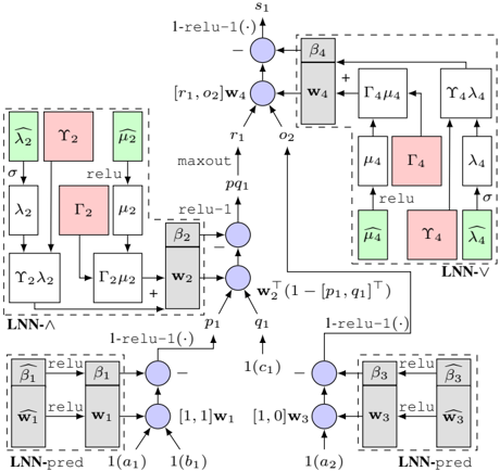
The image depicts a diagram of a Latent Neural Network (LNN) architecture, showcasing the flow of information through various layers and components. The diagram is composed of several interconnected blocks representing different operations and layers within the network. The diagram is grayscale.
### Components/Axes
The diagram consists of several labeled blocks and connections. Key components include:
* **LNN-Λ:** A block labeled "LNN-Λ" enclosed in a dashed box.
* **LNN-V:** A block labeled "LNN-V" enclosed in a dashed box.
* **LNN-pred:** Two blocks labeled "LNN-pred" enclosed in dashed boxes.
* **Boxes with Greek Letters:** Several boxes containing Greek letters (λ, γ, μ, Γ, β) in various colors (red, green, gray).
* **Circles with Plus Signs:** Representing addition operations.
* **Circles with Arrows:** Representing connections and transformations.
* **Rectangles with "relu" and "maxout":** Representing activation functions.
* **Labels:** s1, r1, o2, p1, q1, c1, a1, a2, b1, b2.
* **Weights:** w1, w2, w3, w4.
* **Functions:** l-relu-1(), σ (sigma).
### Detailed Analysis or Content Details
The diagram can be broken down into sections:
**1. LNN-Λ (Top-Left):**
* Input: λ2, γ2, μ2.
* Operations: σ (sigma), relu, Γ2, μ2.
* Output: r1, o2.
**2. Central Processing (Top-Center):**
* Input: r1, o2, w4.
* Operation: maxout.
* Output: p1, q1.
**3. LNN-V (Top-Right):**
* Input: Γ4μ4.
* Operations: relu, γ4, λ4.
* Output: λ4.
**4. LNN-pred (Bottom-Left):**
* Input: a1, w1.
* Operations: relu, β1.
* Output: 1(c1).
**5. LNN-pred (Bottom-Right):**
* Input: a2, w3.
* Operations: relu, β3.
* Output: b1, b2.
**Connections and Functions:**
* l-relu-1() is applied to several outputs.
* w1 is connected to a1 and β1.
* w2 is connected to p1 and q1.
* w3 is connected to a2 and β3.
* w4 is connected to r1 and o2.
* The output of the maxout function (p1, q1) is connected to the LNN-V block.
* The output of the LNN-V block is connected back to the LNN-Λ block via Γ4μ4.
### Key Observations
* The diagram shows a recurrent structure with feedback loops between LNN-Λ and LNN-V.
* The use of multiple activation functions (relu, maxout, l-relu-1) suggests a complex non-linear transformation of the input data.
* The presence of Greek letters within boxes likely represents parameters or latent variables within the network.
* The diagram is highly symbolic and doesn't provide specific numerical values.
### Interpretation
The diagram illustrates the architecture of a Latent Neural Network, designed to learn and represent latent variables within the data. The LNN-Λ block likely functions as an encoder, mapping input data to a latent space. The LNN-V block could be a decoder, reconstructing the input from the latent representation. The LNN-pred blocks likely perform prediction or classification based on the latent variables. The feedback loops suggest a mechanism for refining the latent representation over time. The use of maxout and relu activation functions indicates a desire to capture complex non-linear relationships in the data. The diagram is a high-level representation of the network's structure and doesn't provide details about the training process or specific applications. The diagram is a conceptual illustration of the network's architecture, rather than a concrete implementation. The diagram is a technical illustration of a neural network architecture, likely intended for researchers or engineers working in the field of machine learning.